WengYang Industrial Zone Yueqing Wenzhou 325000
Work Hours
Monday to Friday: 7AM - 7PM
Weekend: 10AM - 5PM
WengYang Industrial Zone Yueqing Wenzhou 325000
Work Hours
Monday to Friday: 7AM - 7PM
Weekend: 10AM - 5PM

Where should surge protection go in a VFD installation? Compare the AC supply, PWM motor output and control circuits, then use a practical SPD selection checklist.
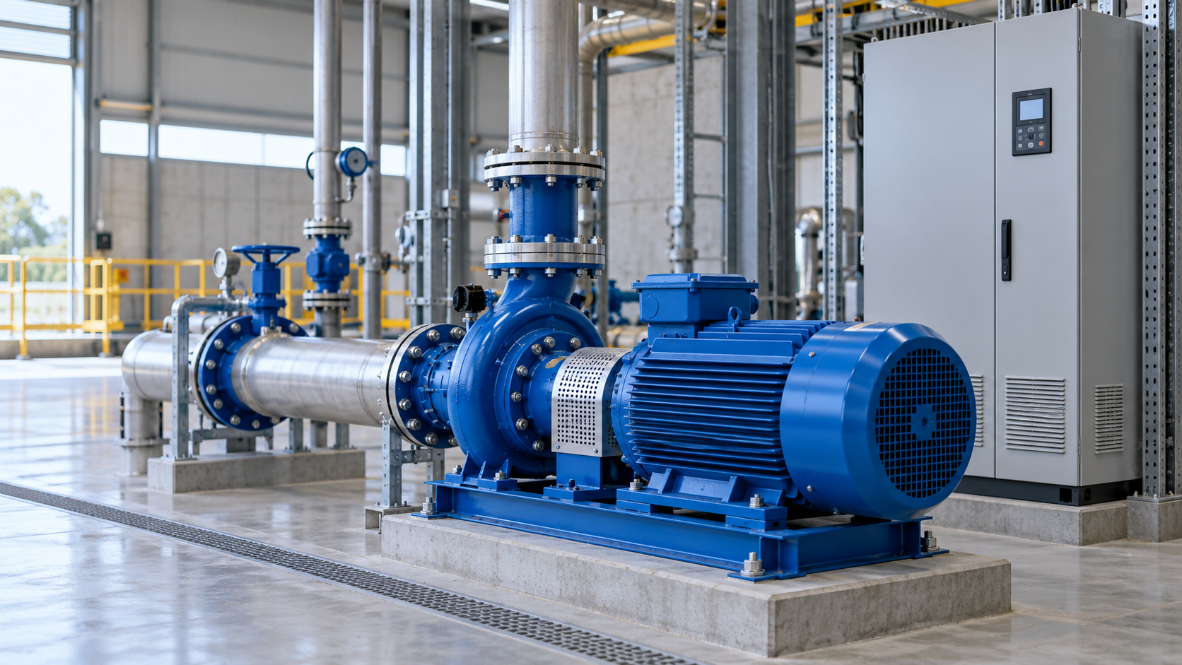
For a conventional variable frequency drive (VFD), evaluate surge protection on the incoming AC supply and the distribution system feeding the drive. Do not assume that a standard AC surge protective device (SPD) can be fitted between the VFD output terminals and the motor. That output is a pulse-width-modulated (PWM) waveform, not an ordinary 50/60 Hz supply. Schneider Electric advises against putting a conventional surge suppressor on the load side of a VFD because the PWM output can damage its components.
The correct arrangement depends on the drive manual, earthing system, lightning exposure, upstream protection and motor-cable design. A qualified electrical designer should verify the complete installation rather than selecting an SPD by its kA rating alone.
| Circuit | What to check | Common mistake |
|---|---|---|
| AC supply to VFD | Coordinate an appropriately rated AC SPD with the supply and drive withstand level. | Assuming any Type 2 SPD is suitable for every panel. |
| PWM output to motor | Follow the drive and motor manufacturers’ requirements for cable length, insulation and output filters. | Installing a standard mains SPD across the motor leads. |
| Control and communications | Review exposed signal lines and their interface ratings separately. | Assuming the power SPD protects every control port. |
IEC 61643-11:2025 addresses SPDs connected to AC low-voltage power systems. It cautions that connection to a different kind of source requires careful consideration of system and fault conditions. A VFD’s PWM output is precisely the kind of non-standard source that calls for product-specific guidance.
Start with the building’s service entrance and the distribution board feeding the VFD. The lightning-protection arrangement and installation rules determine whether a Type 1, Type 2 or coordinated combination is appropriate. If the drive is far from the upstream SPD or its input withstand level requires additional protection, assess a suitable downstream AC SPD near the drive’s line input. This is a design decision, not a universal instruction to install one beside every VFD.
Keep SPD connection conductors as short and direct as the product instructions allow. Extra lead length can raise the effective voltage seen by equipment during a fast transient; Schneider Electric explains the effect of SPD lead length. Check the SPD’s continuous operating voltage (Uc), voltage protection level (Up), discharge ratings, short-circuit suitability and backup protection against the actual panel conditions. Our SPD backup-fuse guide covers the upstream device check.
A VFD repeatedly switches its motor output. Cable reflections and fast voltage edges can stress motor insulation, especially on longer runs. A drive manufacturer may specify a dV/dt filter, sine-wave filter, output reactor or another approved measure for that duty. Those components address repetitive drive-output behavior; a standard AC SPD is designed for a different job. ABB describes the additional motor-voltage stress caused by drive switching and cable reflections.
There are specialised products for certain converter and motor circuits, but they must be explicitly rated for that waveform and application. Do not infer suitability from an IEC AC-SPD label alone. The Schneider Electric VFD guidance is a useful warning for conventional surge suppressors on the output side.
Our SPD indicator guide explains what a healthy-looking status window does and does not prove. For available supply-side devices, see Kuangya AC SPDs. Send the checklist to Kuangya when asking for a suitable product recommendation.
Do not do so without explicit approval from the drive and SPD manufacturers. Conventional AC SPDs are generally intended for AC power circuits, while the output is PWM. Schneider Electric specifically advises against a conventional surge suppressor on the load side of its VFDs.
No. The input SPD addresses transient overvoltage on the supply. An output filter, when specified, addresses repetitive drive-output voltage stress at the motor.
No single placement rule fits every installation. Existing upstream protection, cable distance, equipment withstand level and applicable rules must be assessed together. IEC 61643-12:2020 provides general selection, location and coordination principles for AC power SPDs.

