WengYang Industrial Zone Yueqing Wenzhou 325000
Work Hours
Monday to Friday: 7AM - 7PM
Weekend: 10AM - 5PM
WengYang Industrial Zone Yueqing Wenzhou 325000
Work Hours
Monday to Friday: 7AM - 7PM
Weekend: 10AM - 5PM

A practical engineering guide to Spain’s solar PV protection framework, cold-weather voltage checks, SPD selection, protection coordination, BOM planning and commissioning.
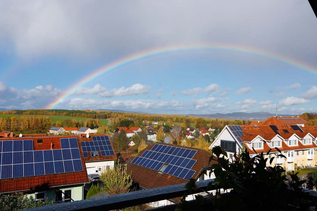
Solar PV protection in Spain raises a simple question with a complicated answer: which protective devices belong between the PV modules, inverter and low-voltage installation?
A safe answer cannot come from a generic product table. It depends on the system voltage, module string design, lightning exposure, building lightning protection, cable routing, inverter characteristics and the rules applicable to the project.
This guide gives installers, EPC engineers and electrical buyers a practical workflow for planning DC-side protection in Spain. It is an engineering aid, not a substitute for the project design, manufacturer instructions or approval by the competent Spanish authority.
Official UNE source — UNE-HD 60364-7-712:2017
Start with the hierarchy, because not every document has the same role.
Spain’s Low Voltage Electrotechnical Regulation, approved by Royal Decree 842/2002, is the national foundation for low-voltage installations. ITC-BT-40 covers low-voltage generating installations, including photovoltaic systems. Royal Decree 244/2019 defines the administrative, technical and economic conditions for electrical self-consumption and modifies parts of ITC-BT-40.
Official BOE source — Royal Decree 842/2002
Official BOE source — Royal Decree 244/2019
Check these official texts against the final system design and the latest consolidated requirements.
For an installer, the practical message is that a PV array is not an isolated collection of modules. It is a generating installation that must be coordinated with the consumer installation, inverter, earthing arrangement, isolation and grid connection.
ITC-BT-23 addresses protection against overvoltages. Its application guide helps designers evaluate when surge protection is required and how protection should be coordinated. The final decision must reflect the actual installation, risk assessment and applicable regional or project requirements.
UNE-HD 60364-7-712:2017 is the Spanish standard for low-voltage PV power-supply systems and is listed as current by UNE. For DC-side surge protection in Spain, UNE-CLC/TS 51643-32:2020 gives selection and application principles for SPDs connected to the DC side of photovoltaic installations. Product selection should also be checked against the relevant product standard, including EN/IEC 61643-31 for PV SPDs.
Do not turn a standards list into a compliance claim. The project engineer must confirm the current editions, amendments, local requirements and the precise scope of each document.
The array’s nominal voltage is not enough. Module open-circuit voltage rises as cell temperature falls, so the design must consider the lowest expected site temperature.
Use the module manufacturer’s Voc and Voc temperature coefficient:
Maximum string Voc = module Voc × modules in series × [1 + |Voc coefficient| × (25°C − minimum design temperature)]
Enter the coefficient as a decimal in the formula. For example, −0.28%/°C becomes 0.0028/°C.
Calculate cold-weather string Voc, check inverter voltage headroom and identify SPD questions that require engineering review. No data leaves this page.
Enter project values and run the screening.
Engineering limitation: This tool is a preliminary screening aid. It does not certify compliance or replace the responsible designer’s assessment under current REBT, UNE requirements, manufacturer instructions and local authority rules.
Example:
The DC isolator, fuse holder, circuit breaker, SPD and inverter input must all have ratings compatible with the real maximum voltage and the manufacturer’s installation conditions. A 1,000 V label must not be accepted automatically when the calculated value leaves inadequate engineering margin.
Parallel strings can feed reverse current into a faulted string. Compare the maximum possible reverse current with the module’s maximum series fuse rating and the conductor’s current-carrying capacity.
The design review should include:
A standard AC fuse or gG fuse should not be treated as interchangeable with a gPV fuse simply because a DC voltage appears on the label. PV fault-current behaviour and the intended utilization category matter.
A useful preliminary decision tree is:
This is a screening workflow, not a lightning-risk calculation. The final design must follow the applicable lightning protection and electrical installation standards.
For the PV side, verify at least:
Ucpv is above the maximum calculated array voltageUp is compatible with the inverter impulse withstand levelAn SPD with a good data sheet can still provide poor protection if installed with long, looped connecting conductors. Lead inductance adds residual voltage during a fast surge.
Keep connections short and direct, avoid unnecessary loops and follow the SPD and inverter manufacturers’ instructions. When the distance between the array-side protection and inverter becomes significant, assess whether coordinated SPDs are needed at both ends of the DC cable. The applicable standard and project risk assessment should determine the exact arrangement.
The DC protection system should be reviewed as one assembly rather than as independent products.
| Function | Typical device | Essential checks |
|---|---|---|
| String overcurrent protection | gPV fuse and holder | Current, maximum string voltage, utilization category, breaking capacity, thermal derating |
| Array or feeder protection | DC MCB/MCCB where applicable | DC poles, voltage per pole, trip curve, breaking capacity, polarity requirements |
| Safe isolation | DC switch-disconnector | DC-PV utilization category, voltage, current, poles, load-breaking capability |
| Transient overvoltage protection | PV DC SPD | Type, Ucpv, In/Imax or Iimp, Up, topology, backup protection |
| Equipment protection | Inverter input protection | Maximum input voltage/current, internal SPD details, manufacturer coordination |
| Earthing and bonding | PE/bonding conductors | Topology, conductor sizing, routing, continuity and test requirements |
A typical design may begin with a PV Type 2 SPD, a correctly rated DC isolator and string fuses only where the parallel-string and module calculations require them. Confirm the inverter’s internal protection; “SPD included” does not automatically mean the entire external installation is protected.
The designer must assess separation distance and lightning-current paths. Where separation is not maintained and lightning current may be introduced, a Type 1 or Type 1+2 PV SPD may be required as part of a coordinated lightning and surge protection concept. Equipotential bonding, cable routing and SPD placement become critical.
Long DC routes, multiple combiner boxes and a distributed earthing network increase coordination complexity. The design may require SPDs at combiner and inverter locations, gPV string fuses, monitored switch-disconnectors and remote SPD status contacts. Selectivity and maintenance access should be designed before the BOM is frozen.
Use this table when requesting quotations. Complete every blank field with project data.
| Item | Required project value | Supplier evidence |
|---|---|---|
| System maximum voltage | ___ V DC | Calculation and module data sheet |
| Number of strings / inputs | ___ / ___ | Single-line diagram |
| PV SPD | Type ___; Ucpv ___ V; Up ≤ ___ kV | Data sheet, test standard, certificate/report |
| gPV fuse | ___ A; ___ V DC; size ___ | Time-current curve and power-loss data |
| Fuse holder | ___ A; ___ V DC | Temperature derating and terminal data |
| DC isolator | ___ A; ___ V DC; ___ poles | DC-PV utilization category |
| DC breaker/MCCB | ___ A; ___ V DC; Icu/Ics ___ kA | DC wiring/pole configuration |
| Enclosure | IP ___; IK ___ | Temperature/UV/corrosion suitability |
| Monitoring | SPD/fuse/switch status | Contact ratings and protocol |
Cold-weather Voc can exceed the value assumed from nominal voltage. Calculate first and select second.
SPD type is determined by the lightning-current and coordination requirements. A higher product label does not correct poor placement, excessive lead length or an incompatible voltage protection level.
DC arc extinction, pole configuration, polarity and switching duties differ. Use devices whose DC application and wiring are explicitly documented.
Combiner boxes exposed to Spanish sun can operate far above ambient air temperature. Check the thermal power loss of fuses, holders and SPDs, enclosure ventilation strategy and manufacturer derating data.
A certificate is useful only when the exact model, standard, ratings and manufacturing identity match the quoted product. Request traceable technical documentation.
The answer depends on the applicable REBT provisions, risk assessment, installation characteristics and project requirements. The competent designer should document the decision rather than relying on a universal yes/no statement.
Type 2 is a common starting point where lightning-current discharge capability is not required. Where an external LPS and the separation assessment indicate that lightning current can enter the installation, evaluate Type 1 or Type 1+2 protection. Confirm the design under the applicable standards.
No. Calculate maximum cold-weather string Voc, then verify Ucpv, PV topology, short-circuit behaviour, protection level and manufacturer conditions. A nominal “1,000 V system” description is insufficient.
Not automatically. Check the inverter’s SPD type, location, replaceability and coordination with cable length and the rest of the installation.
Request model-specific data sheets, applicable test standards, traceable conformity documentation, wiring instructions, temperature derating, backup-protection requirements and production-quality records.
Reliable PV protection begins with real project inputs: site temperature, string voltage, parallel-string current, lightning context, cable routes and inverter limits. Once those values are known, the SPD, fuse, isolator, breaker and enclosure can be coordinated as a system.
Kuangya supplies DC protection components for solar PV applications, including PV SPDs, gPV fuses and holders, DC circuit breakers, switch-disconnectors and combiner-box solutions. Send us your module data sheet, string layout, inverter model, site temperature range and single-line diagram to receive a project-specific BOM proposal.
Engineering note: Product recommendations must be verified by the responsible project designer and local authority. This article does not certify compliance for a specific installation.

