WengYang Industrial Zone Yueqing Wenzhou 325000
Work Hours
Monday to Friday: 7AM - 7PM
Weekend: 10AM - 5PM
WengYang Industrial Zone Yueqing Wenzhou 325000
Work Hours
Monday to Friday: 7AM - 7PM
Weekend: 10AM - 5PM
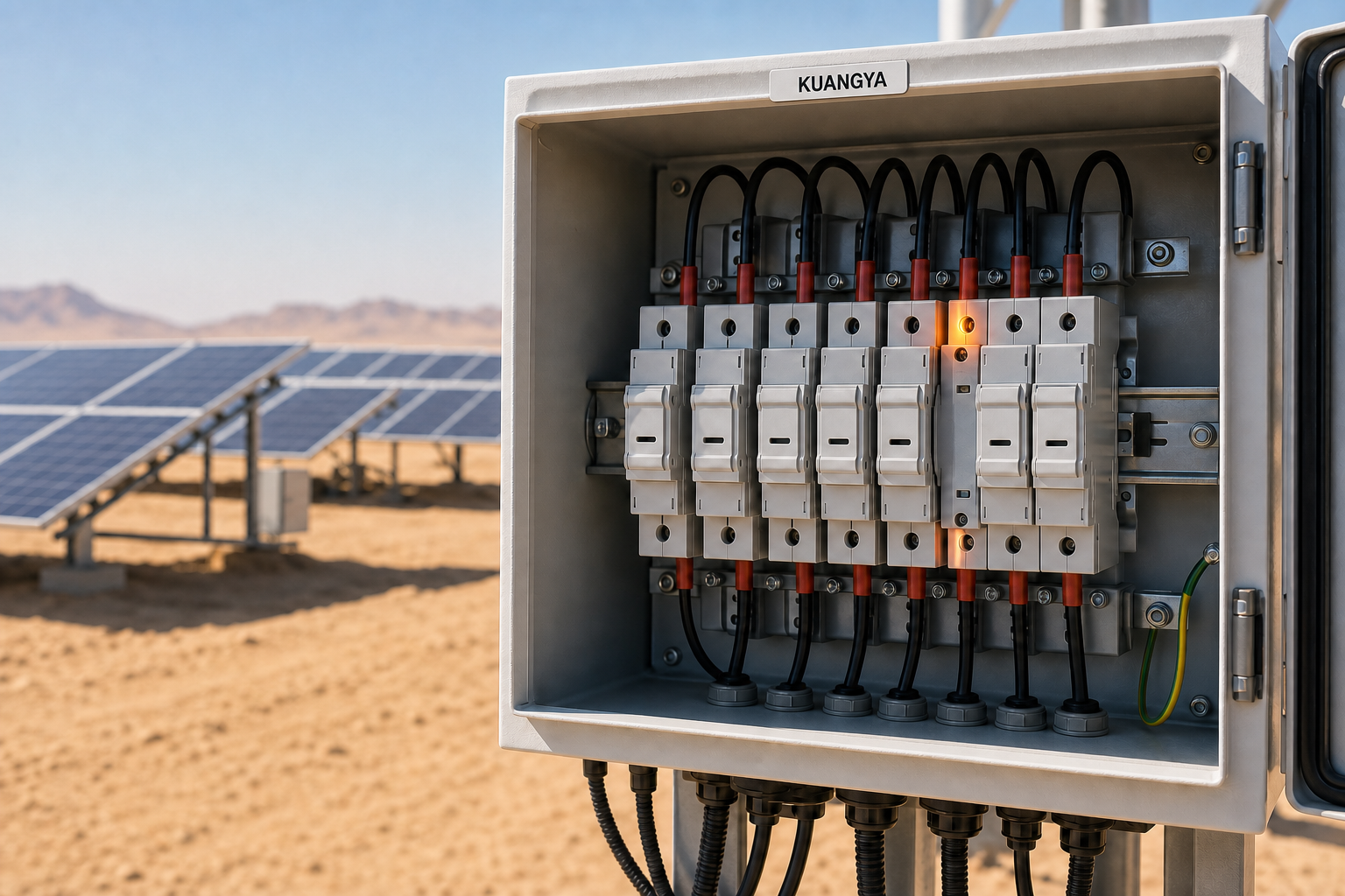
PV fuse holder overheating is not simply a “hot weather” problem. In a solar combiner box, heat is produced by the fuse link, contact resistance, terminals and conductors, then trapped by the enclosure. When high ambient temperature, dust, weak ventilation or an incorrect component match is added, a small thermal margin can disappear quickly.
This is especially important in Saudi Arabia, the UAE, Oman, Qatar and other hot-climate markets. A combiner box exposed to direct sun can operate at a much higher internal temperature than the published outdoor air temperature. The result may be nuisance fuse operation, discolored plastic, damaged insulation, unstable contact pressure or, in severe cases, a local thermal event.
This guide explains seven common causes of solar fuse holder overheating, how to diagnose them, and what EPC and procurement teams should verify before approving 1000V or 1500V gPV fuse assemblies.
Every current-carrying connection has resistance. The heat produced at a connection follows the relationship:
Power loss = Current² × Resistance
This matters because a modest increase in resistance can create a large temperature rise when the circuit operates near its continuous-current limit. A gPV fuse link also has intentional resistance because it must melt safely under defined fault conditions. The holder must carry that current, maintain reliable contact pressure and release the heat to the surrounding air.
The fuse link and holder therefore behave as one thermal assembly. Selecting each item only by its headline current rating is not enough.
One of the most common mistakes is treating a 32A or 63A holder rating as a guaranteed continuous operating current under every condition. Laboratory ratings are established under defined test conditions. A closed combiner box in a desert installation may have less airflow, more adjacent heat sources and a much higher internal ambient temperature.
Eaton notes that fuse holders generally require derating and that temperature, current cycling, enclosure conditions and airflow can require additional margin. Its photovoltaic application guidance also states that extra derating may be necessary when a fuse is installed in a high-temperature environment.
A fuse link may physically fit inside a holder but still be a poor thermal match. Different fuse links can have different power dissipation, end-cap dimensions, surface finishes and operating characteristics. A mixed assembly may develop higher contact resistance or transfer more heat into a holder than it was designed to manage.
The risk is greater when a project combines:
IEC 60269-6 defines supplementary requirements for fuse links used to protect PV strings and arrays up to 1500V DC. A project should verify the complete assembly and its application data, not rely on appearance alone.
Ask the supplier for a declared fuse-link/holder pairing, voltage rating, current range, power-loss data, applicable standard and temperature limits. For OEM combiner boxes, freeze the approved combination in the bill of materials so production cannot substitute one half of the assembly without engineering review.
A loose screw terminal produces a high-resistance connection. Because heating rises with current squared, even a small increase in terminal resistance can produce a concentrated hot spot. Repeated daily heating and cooling can then worsen the connection.
Common causes include:
Use the manufacturer’s tightening torque and conductor-range data. Record torque during production or commissioning, then inspect a sample after thermal cycling. If thermal imaging shows one hot terminal while the fuse body remains comparatively cool, investigate the connection before changing the fuse rating.
Never open or service a live DC fuse holder. Isolate the source, follow the project lockout procedure and confirm absence of voltage using an appropriate method.
Direct solar radiation can turn an outdoor enclosure into a heat trap. Dark enclosure surfaces, limited spacing, tightly packed DIN-rail devices and poor internal circulation all raise component temperature. The local temperature beside a row of fuse holders may be substantially higher than the air outside the box.
Hot-climate design should also consider:
Abu Dhabi’s solar PV installation guidance emphasizes equipment and cabling suitable for the installation environment, high temperature and UV exposure. The same environmental thinking should be applied to protection assemblies inside outdoor enclosures.
Model or measure the worst-case internal temperature. Provide spacing according to the equipment instructions, use a suitable enclosure color and sun shield, and avoid placing the combiner box where heat cannot escape. When required, validate the completed assembly with temperature-rise testing at representative load.
Fine desert dust can enter during installation or maintenance. Coastal projects may also face humidity and airborne salt. Contamination can affect terminals, contact surfaces and insulation, while corrosion gradually increases resistance.
The symptom may not be uniform heating. A contaminated or corroded contact often creates a localized temperature difference between otherwise identical strings.
An adequately rated cable can still create a bad connection if its construction does not match the terminal. Oversized conductors may not seat correctly; undersized conductors may not be clamped securely. Poorly crimped ferrules add another resistive interface.
Also check the terminal temperature rating. Eaton’s PV application guide warns that component, terminal and conductor temperature ratings must be coordinated. Using a 90°C cable does not automatically permit every connected terminal to operate at 90°C.
Verify:
Not every hot fuse holder is caused by the holder. Higher-than-expected current, reverse current from parallel strings, an intermittent fault or an incorrect string configuration can raise the fuse temperature. Replacing the holder without finding the electrical cause may only reset the clock.
Compare current between similar strings and review inverter data, module configuration, polarity and insulation-test results. A recurring problem on one circuit deserves electrical investigation, not just another replacement part.
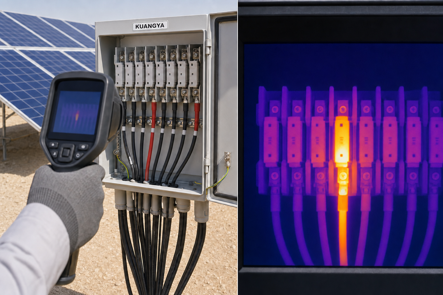
Use this sequence during a planned, safe inspection:
| Check | What to compare | Possible finding |
|---|---|---|
| Thermal image | Identical holders under similar load | One hot unit suggests a local connection or component issue |
| String current | Current across parallel strings | Abnormal current may indicate a circuit problem |
| Terminal temperature | Cable terminal vs. fuse body | A terminal hot spot suggests connection resistance |
| Visual condition | Color, cracking, corrosion, pitting | Heat or environmental damage |
| Torque records | Actual vs. specified torque | Installation inconsistency |
| Part numbers | Fuse link, holder, voltage and size | Mismatched assembly |
| Enclosure temperature | Internal vs. external ambient | Insufficient thermal margin |
Thermal comparisons should be made under similar load and environmental conditions. A temperature value without load context can be misleading.
For a Middle East project, the purchase specification should include more than voltage and current:
For string-level applications, compact cylindrical formats such as 10×38, 14×51, 10×85 and 14×85 may be used according to voltage and current requirements. High-current combiner, inverter or energy-storage circuits may require square-body fuse systems. The format must be selected from actual circuit conditions rather than panel space alone.
Replace the holder if it shows melted or discolored plastic, loss of contact pressure, damaged terminals, pitting, corrosion, cracking or recurring abnormal temperature after the external cause has been corrected. Replace the associated fuse link if it has experienced abnormal heat or if the manufacturer requires replacement as an assembly.
Do not reuse a heat-damaged holder simply because it still conducts electricity. Thermal damage can change spring force, insulation strength and creepage performance.
PV fuse holder overheating usually comes from a combination of current, resistance and insufficient heat dissipation. In desert solar projects, the design must account for the real enclosure temperature, a verified gPV fuse-link/holder match, terminal workmanship, contamination and maintenance access.
A reliable specification connects the electrical calculation to the complete installed assembly. That approach reduces nuisance failures, improves traceability and gives EPC and O&M teams a practical basis for thermal inspection.
KUANGYA supplies 1000V and 1500V gPV fuse links and matching fuse holders for photovoltaic strings, combiner boxes, inverters and energy-storage DC circuits. Share your system voltage, string Isc, target current, enclosure temperature and preferred fuse format with our engineering team for a component recommendation.
Explore KUANGYA PV fuses and holders: https://cnkuangya.com/dc-fuse/
Some temperature rise is normal because the fuse link and contacts have resistance. However, a holder that is much hotter than identical neighboring units, shows discoloration or produces odor requires investigation. Judge temperature together with load, ambient conditions and manufacturer limits.
Not without a complete protection review. A larger fuse may fail to protect the module wiring or conductor correctly. First identify whether the cause is ambient temperature, derating, a loose connection, a mismatched holder or abnormal circuit current.
Generally, yes. The required margin depends on the specific fuse link, holder, airflow, enclosure temperature, spacing and current cycling. Use manufacturer data and validate the completed assembly under realistic conditions.
IEC 60269-6 provides supplementary requirements for fuse links used to protect photovoltaic strings and arrays in DC circuits up to 1500V.
Send the maximum system voltage, module Voc and Isc, number of parallel strings, desired fuse current, conductor size, enclosure temperature, installation format and applicable project standard.
