温州市岳陽工業区 325000
勤務時間
月曜日~金曜日:午前7時~午後7時
週末午前10時~午後5時
温州市岳陽工業区 325000
勤務時間
月曜日~金曜日:午前7時~午後7時
週末午前10時~午後5時

A surge protective device (SPD) can reach the end of its service life without interrupting the power supply. The connected equipment may continue operating normally, even though one of its intended surge protection paths is no longer available.
For installations that cannot rely on regular visual inspections, this creates an important maintenance challenge.
How can an electrical panel report an SPD fault before someone opens the cabinet?
The answer is SPD remote signaling.
By using auxiliary signaling contacts, a compatible surge protective device can communicate its monitored status to an alarm circuit, programmable logic controller (PLC), or building management system (BMS).
However, three small terminal markings often cause confusion: COM, NO, and NC.
Understanding these contacts is essential for designing a reliable monitoring circuit.
This guide explains how SPD remote signaling works, what the contact markings mean, how to integrate them into a monitoring system, and what engineers and buyers should verify before installation.
SPD remote signaling is a function that allows a surge protective device to communicate a monitored operating or fault status to external equipment.
Many modular SPDs include a mechanical status indicator on the front of the device.
Depending on the manufacturer, this indicator may display:
A visual indicator is useful during routine maintenance, but it requires someone to inspect the electrical panel.
Remote signaling extends this indication beyond the cabinet.
When an SPD’s monitored status changes, its auxiliary signaling contact can change state. An external monitoring circuit can then detect the change and generate an alarm.
The remote signaling contact does not divert surge current. Its function is to communicate status.
For example, a distribution cabinet may contain an SPD connected to a PLC digital input.
If the SPD’s internal disconnector operates and the signaling mechanism changes state, the PLC can receive that information and display a maintenance warning.
This helps maintenance personnel identify an SPD requiring attention without continuously inspecting every electrical cabinet.
For a broader explanation of SPD protection and maintenance, see our guide to surge protective devices and their applications.
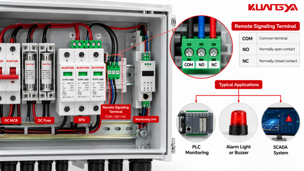
Many SPDs with remote signaling use a changeover contact with three connection terminals.
These terminals are commonly identified as COM, NO, and NC.
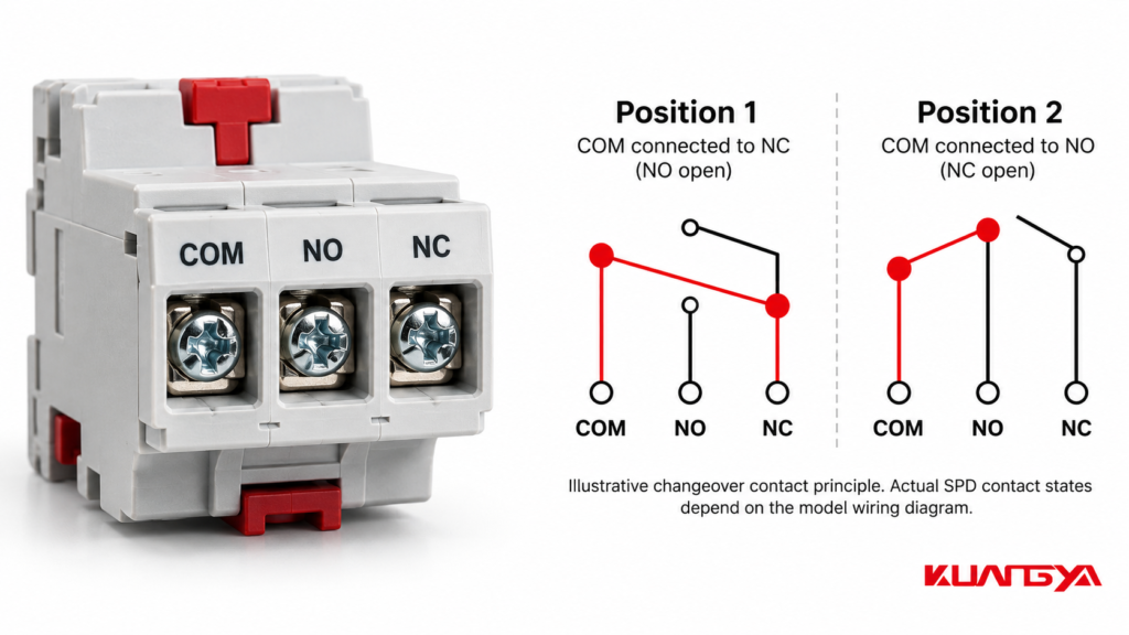
| ターミナル | 意味 | 機能 |
|---|---|---|
| COM | 共通 | Shared terminal of the changeover contact |
| ノー | Normally Open | Contact designated as open in its defined reference state |
| NC | Normally Closed | Contact designated as closed in its defined reference state |
COM is the common connection point of the changeover contact.
Depending on the contact position, COM connects to either the NO or NC terminal.
In a monitoring circuit, COM may be connected to an appropriate control voltage or signal reference, provided the circuit complies with the contact ratings and monitoring equipment requirements.
NO means Normally Open.
For a conventional changeover contact, the NO path is open in the contact’s defined reference position and closes when the contact transfers.
However, an important distinction must be made when applying this terminology to an SPD.
NO does not automatically mean that the contact is open when the SPD is healthy.
The SPD manufacturer may define the contact’s mechanical reference position differently from the device’s installed, healthy operating state.
NC means Normally Closed.
In the contact’s defined reference position, the NC path is closed to COM.
When the contact changes position, that connection opens.
Again, the SPD’s normal operating state must be verified using its actual wiring diagram.
Do not assume that COM–NC is always closed when the SPD is healthy or that COM–NO always closes when the SPD fails.
The contact labels describe the switching terminals. The manufacturer’s documentation establishes how those terminals behave in the SPD’s actual operating conditions.
Remote signaling is commonly associated with a mechanical status indication or internal disconnection mechanism.
In many modular SPDs, surge protection components are monitored through an internal mechanism that responds when a defined abnormal or end-of-life condition occurs.
A typical sequence is:
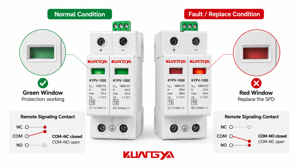
The exact behavior depends on the SPD design.
Some signaling arrangements monitor multiple protection modules through a common alarm contact. Others may offer different signaling configurations.
It is also important to understand what the remote contact does not measure.
A conventional mechanical remote signaling contact is not a surge counter, a continuous MOV health analyzer, or a real-time measurement of remaining surge capacity.
It typically reports the condition recognized by the device’s monitoring mechanism.
Therefore, a normal contact state does not guarantee that every electrical characteristic of the SPD remains identical to its original factory-tested condition.
Before connecting an SPD to external monitoring equipment, engineers should establish the relationship between the SPD status and contact continuity.
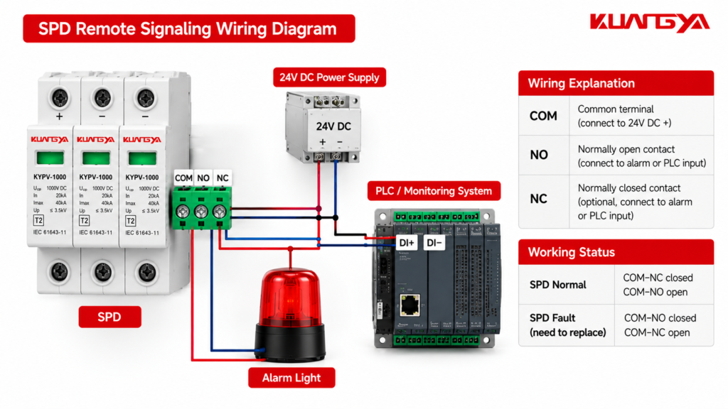
The following table illustrates one possible signaling arrangement.
Illustrative example only — not a universal SPD terminal specification.
| SPD condition | COM–NO | COM–NC | Monitoring interpretation |
|---|---|---|---|
| Normal monitored condition | Open | Closed | ノーマル |
| Fault or replacement condition | Closed | Open | Alarm |
In this example, the monitoring system could use the COM–NO connection to detect a fault by observing contact closure.
Alternatively, the COM–NC connection could be used to monitor the opening of the normally closed path.
But another SPD model may use the opposite operating-state relationship.
For this reason, designers must confirm the correct contact states using the specific SPD’s manufacturer-supplied diagram.
A changeover contact does not simply provide two independent alarm outputs.
Under its defined switching conditions, the common terminal changes its connection from one contact path to the other.
For a typical break-before-make mechanical changeover contact, the two paths are not intended to remain closed simultaneously.
The monitoring equipment can detect the relevant change as a digital input.
However, the interpretation of that input must be programmed according to the chosen wiring arrangement.
One common application is connecting an SPD’s auxiliary contact to a PLC digital input.
This allows the PLC to identify a monitored fault condition and display an alarm through an HMI or supervisory system.
Consider an industrial cabinet using a 24 V DC PLC input circuit.
A simplified conceptual arrangement is:
Control supply → SPD signaling contact → PLC digital input
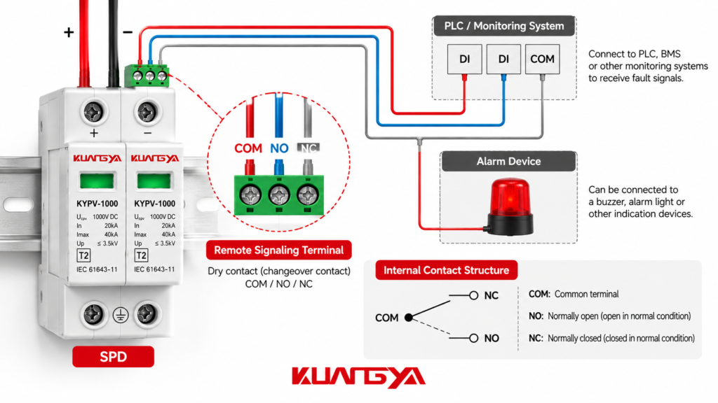
The contact itself functions as a switching element.
For example, an engineer may connect an appropriately rated control supply through the SPD’s selected auxiliary contact to the PLC input, with the corresponding input common connected as required by the PLC manufacturer’s instructions.
The actual circuit depends on whether the PLC input is sinking, sourcing, or otherwise configured.
Not every SPD includes remote signaling as standard equipment.
Some manufacturers provide the function through an optional contact or a separate product variant.
Check the SPD model number and technical documentation before designing the control circuit.
For example, selected KUANGYA Type 2 surge protective devices offer optional remote signaling contacts for monitoring integration.
Locate the actual wiring diagram for the SPD model.
Confirm:
Terminal numbers should be taken from the specific product documentation, not copied from a different SPD model.
A dry contact is not necessarily suitable for every voltage or current.
Check the maximum switching voltage, switching current, and applicable AC/DC ratings.
Also verify any minimum switching load requirements, particularly when connecting low-current electronic inputs.
The contact must not be used directly to switch an electrical load exceeding its specified ratings.
Use the selected contact path according to the intended alarm logic.
For example, a monitoring system may use a contact that opens when a monitored fault occurs.
The PLC can then interpret that change as an alarm condition.
Alternatively, the system may use a contact that closes upon the monitored fault condition.
Neither arrangement should be treated as universally correct.
The choice depends on the manufacturer’s contact-state diagram and the monitoring system design.
The PLC program should interpret the input signal according to the verified contact behavior.
Possible displayed messages include:
Where necessary, add alarm delays or input filtering to avoid nuisance indications from brief signal disturbances.
Do not automatically identify every input change as confirmed SPD failure. An open wire, disconnected terminal, or monitoring-system fault may produce a similar signal.
The complete circuit should be checked by qualified electrical personnel.
Where supported by the manufacturer, safely simulate the defined signaling condition and confirm that:
Do not intentionally damage an SPD or apply a surge to test its remote signaling function.
There is no universal answer.
The better choice depends on the required alarm logic, contact behavior, and monitoring architecture.
A common engineering preference is to use a normally energized or closed monitoring loop where interruption can be interpreted as a fault.
This approach may help detect certain wiring failures, such as a broken monitoring conductor.
For example, if an alarm input is designed to remain active while the monitoring loop is intact, a broken wire can cause a change similar to an SPD fault.
However, this does not provide complete wire supervision.
An ordinary single-input contact circuit may not distinguish between:
A short circuit across the monitoring pair may also remain undetected in a simple two-wire circuit.
For systems requiring more comprehensive fault detection, engineers may use supervised input modules or other diagnostic arrangements.
The correct objective is not simply to choose NO or NC. It is to ensure that the entire monitoring circuit responds predictably to both equipment faults and relevant wiring failures.
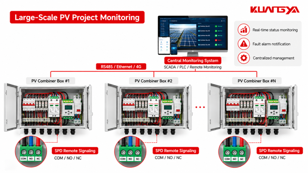
Large industrial facilities may contain numerous electrical cabinets.
Inspecting every SPD manually can be time-consuming.
Remote signaling enables maintenance teams to incorporate SPD status information into centralized monitoring systems.
Solar installations may contain multiple PV combiner boxes distributed across a large area.
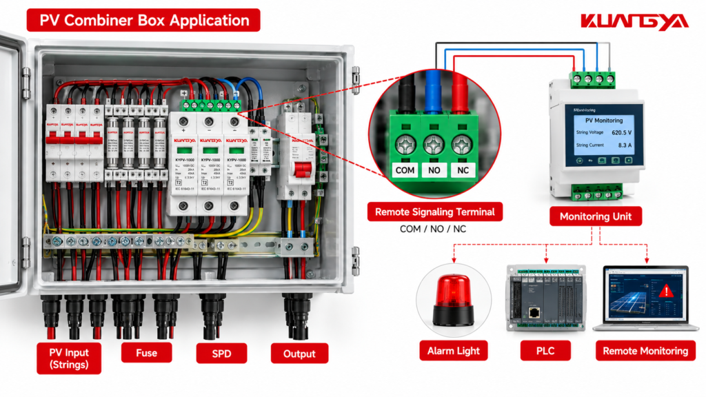
An SPD installed inside a combiner box may be difficult to inspect frequently.
Where compatible remote contacts and monitoring inputs are provided, the SPD status can be integrated into the site’s monitoring system.
This arrangement can help maintenance teams identify which cabinet requires inspection.
However, SPD remote signaling should not be confused with complete PV string monitoring.
It does not independently measure string current, voltage, or power output.
Facilities with high equipment availability requirements often use centralized alarm systems.
SPD status information can support preventive maintenance by identifying a monitored protection fault.
The remote contact is a maintenance indication and should not be mistaken for proof of complete equipment protection.
In commercial buildings, SPD contacts may be connected to appropriate BMS digital inputs.
This allows maintenance personnel to view surge protection fault indications alongside other electrical system alarms.
EV charging installations can involve outdoor equipment, distributed cabinets, and remote maintenance teams.
Where compatible SPDs and monitoring systems are installed, remote fault indication can help identify devices requiring inspection.
Remote signaling and surge counting are sometimes confused because both involve SPD monitoring.
However, they provide different information.
| 特徴 | SPD Remote Signaling | Surge Counter |
|---|---|---|
| 主機能 | Reports defined SPD status changes | Counts detected surge events |
| Typical output | Contact state or alarm signal | Event count or recorded data |
| Indicates module replacement condition | Often, if designed for it | 必ずしもそうとは限りません |
| Counts surge events | いいえ | はい |
| Can connect to remote monitoring | Yes, with suitable interface | Depends on model |
| Measures remaining SPD life | Generally no | Generally no |
A surge counter may record transient events without determining whether an SPD must be replaced.
Similarly, an SPD remote alarm may indicate an internal disconnection or fault without revealing how many surge events the device has experienced.
These functions are complementary rather than interchangeable.
The most common mistake is interpreting terminal markings without checking the operating-state diagram.
NO and NC labels alone do not establish which terminal pair will be closed when the SPD is healthy.
Always confirm the model-specific contact arrangement.
Remote signaling contacts are normally intended for signaling applications.
They are not intended to directly switch high-power equipment unless explicitly rated for that duty.
Check the electrical ratings before connecting external devices.
The main SPD power terminals and the auxiliary signaling terminals serve different functions.
The auxiliary contact must not be used as part of the surge discharge path.
Maintain suitable wiring separation, insulation coordination, and installation practices according to the equipment instructions and applicable regulations.
A remote contact reports only the condition its mechanism is designed to monitor.
It does not replace appropriate electrical inspection, manufacturer-recommended testing, or maintenance procedures.
For more information, read our guide to SPD backup fuse selection to understand how surge protection and overcurrent protection work together.
An improperly designed alarm circuit may fail to report a disconnected signal cable or loss of control voltage.
Where reliability is important, include monitoring-circuit fault detection in the overall control design.
A basic continuity test can help verify the state of an accessible mechanical signaling contact.
However, it must be performed correctly.
重要: Electrical testing should only be performed by qualified personnel using appropriate isolation, lockout, and verification procedures.
A safe general process is:
Do not attempt to operate internal SPD components manually unless the manufacturer specifically permits that procedure.
Also, remember that a continuity test verifies the contact’s electrical state only.
It does not prove the SPD can still withstand its specified surge current.
For panel manufacturers, electrical distributors, and project procurement teams, remote signaling should be considered during product selection.
A suitable purchasing checklist includes:
| 項目 | What to Confirm |
|---|---|
| SPD application | AC or DC system |
| SPD classification | Type 1, Type 2, or Type 1+2 |
| 定格電圧 | Suitable Uc or Ucpv |
| Discharge performance | Required Iimp, In, Imax, and Up |
| Remote signaling | Included or optional |
| Contact configuration | COM/NO/NC or other specified interface |
| Contact ratings | Permitted AC/DC switching values |
| 監視インターフェース | PLC, BMS, alarm relay, or other input |
| Contact-state diagram | Normal, fault, and relevant disconnected conditions |
| メンテナンス | Replaceable module availability |
| ドキュメンテーション | Datasheet, wiring diagram, and applicable test documentation |
One purchasing detail is particularly important.
An SPD with remote signaling is not necessarily the same product variant as an otherwise identical SPD without remote signaling.
Confirm the exact ordering code and configuration before production or shipment.
For projects requiring specific alarm functions, the manufacturer should provide the appropriate contact diagram and electrical ratings for approval.
At KUANGYA, we supply surge protective devices for a range of low-voltage electrical applications, including industrial distribution and equipment protection.
Selected KUANGYA SPD models offer optional remote signaling contacts for integration with external monitoring systems.
For example, our Type 2 Surge Protection Device product information includes optional remote contact specifications.
We also offer Type 1+2 Surge Protective Devices with remote signaling options for suitable applications.
For system designers, the most important step is selecting the correct SPD electrical ratings and confirming that the requested signaling configuration matches the monitoring requirements.
When requesting a quotation, customers can share:
Our team can help review the requested product configuration and provide available technical documentation for the selected model.
Explore more electrical protection products and solutions at クアンニャ.
SPD remote signaling allows a compatible surge protective device to report a defined monitored status to external equipment, such as a PLC, alarm system, or building management system.
It helps maintenance personnel identify devices requiring attention without relying only on local visual inspection.
COM means Common, NO means Normally Open, and NC means Normally Closed.
These are conventional markings for changeover contacts.
The actual contact state during normal SPD operation or failure must be verified from the specific manufacturer’s wiring diagram.
A conventional potential-free mechanical contact does not require external power to perform its basic switching function.
However, the connected PLC, alarm circuit, or monitoring device normally needs a suitable power source to detect and communicate the contact state.
Not all SPD monitoring interfaces are mechanically passive contacts, so the product documentation must be checked.
A suitable potential-free signaling contact can often be integrated into a PLC digital input circuit.
The designer must confirm voltage, current, input configuration, insulation requirements, and the contact’s documented operating logic.
そうだ。.
A conventional remote signaling contact generally reports a defined protection-status or disconnection condition.
It does not count every surge event or continuously measure all changes in SPD performance.
そうだ。.
For small installations with accessible distribution boards, local status indication may be sufficient.
Remote signaling becomes particularly useful in industrial facilities, distributed solar installations, unattended electrical cabinets, and systems requiring centralized maintenance alarms.
In many parallel-connected SPD arrangements, the protected equipment can continue receiving power after an SPD protection element disconnects.
This means that an SPD fault may go unnoticed unless the device is inspected or monitored.
Remote signaling can help identify the condition recognized by the SPD’s monitoring mechanism.
Yes, an appropriate multimeter can check continuity across accessible, isolated mechanical contact terminals.
However, this does not test the SPD’s rated surge protection performance.
Always follow the manufacturer’s electrical safety instructions.
SPD remote signaling adds an important monitoring function to electrical surge protection systems.
By understanding COM, NO, and NC terminals, engineers can integrate compatible SPDs with PLCs, alarm circuits, and building monitoring systems.
However, correct wiring requires more than recognizing the contact labels.
The contact-state diagram, switching ratings, monitoring logic, and installation requirements must all be verified for the exact SPD model.
For panel builders and procurement teams, confirming these details before ordering can prevent incorrect alarm operation and unnecessary commissioning problems.
Looking for surge protective devices with remote signaling options?
Contact KUANGYA to discuss your electrical system requirements, SPD configuration, and monitoring interface.
ウェブサイト www.cnkuangya.com
For additional technical information, consult the following resources:
Technical note: Terminal functions, contact ratings, and normal/fault switching positions vary by product. Always use the exact manufacturer’s wiring diagram for final installation and commissioning.

