温州市岳陽工業区 325000
勤務時間
月曜日~金曜日:午前7時~午後7時
週末午前10時~午後5時
温州市岳陽工業区 325000
勤務時間
月曜日~金曜日:午前7時~午後7時
週末午前10時~午後5時

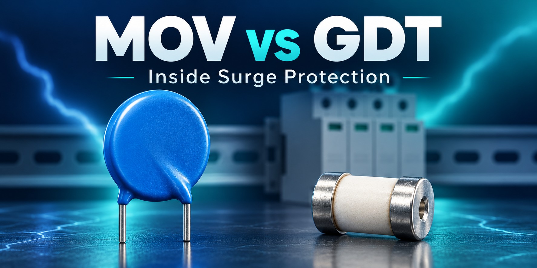
MOV vs GDT is an important comparison when evaluating surge protective devices. A metal oxide varistor limits voltage through a nonlinear resistance characteristic. A gas discharge tube switches into a conducting state when the gas inside ionizes. Both can form part of an SPD, but neither component name proves that a finished device is suitable for your installation.
This guide explains the practical differences, why manufacturers combine the technologies, and which specifications buyers should request before approving a product.
| 特徴 | MOV | GDT |
|---|---|---|
| Full name | Metal oxide varistor | Gas discharge tube |
| Basic behavior | 電圧制限 | Voltage switching |
| Important voltage data | Continuous voltage rating and clamping voltage at a stated current | DC and impulse sparkover characteristics |
| Design considerations | Leakage, surge stress and thermal protection | Sparkover behavior and extinction of follow current |
| Selection rule | Evaluate the complete protective circuit and its tested ratings | |
An MOV normally presents a high resistance at its intended operating voltage. Its conduction increases sharply as the applied voltage rises. During a surge, this nonlinear behavior helps limit the voltage across the protected circuit. It is not an ideal switch with one perfectly fixed clamping voltage.
When comparing datasheets, distinguish the continuous operating-voltage rating, the varistor voltage measured at a specified test current, and the clamping voltage at a specified surge current. These numbers describe different conditions. フエニックス・コンタクトのサージ保護の基礎 explains the distinction between voltage-limiting and voltage-switching technologies.
A GDT contains electrodes separated by a gas-filled gap. Before sparkover, it has a high insulation resistance. When the applied voltage causes ionization, it enters a conducting state and can divert surge current through the designed protective path.
GDTs can offer low capacitance, which is useful in some signal applications. However, the selected component still needs to match the interface and its electrical limits. Bourns’ GDT overview describes these characteristics and their use in protection circuits. Do not assume every GDT package has the same surge capability.
After a voltage-switching device fires, the normal power source may continue to drive current through the conducting path. This is different from the original transient. The protective design must allow that current to extinguish under the intended supply conditions.
A circuit that behaves acceptably on one supply may not behave the same way on another. In particular, a DC application cannot rely on the natural current zero crossings of AC. Check the complete device’s declared AC or DC application instead of extrapolating from the presence of a GDT.
Bourns’ explanation of its IsoMOV hybrid components describes how the MOV and GDT cooperate to address leakage and follow-on current in that specific design. These benefits belong to an engineered combination, not to an arbitrary pair of components connected together.
Manufacturers may use a series combination to reduce the MOV’s exposure to normal operating voltage and its associated leakage. The circuit must still provide suitable surge behavior when the GDT fires. The result depends on the selected parts and their coordination.
TDK’s integrated MOV-GDT example shows this approach at component level. It is evidence that the technologies can complement each other; it is not a reason to label every hybrid SPD better than every MOV-based SPD.
Ask the supplier for tested performance of the finished device. A hybrid label alone does not establish its voltage protection level, permitted installation location, or service life.
Surge exposure and abnormal voltage conditions can stress an MOV. The device design therefore needs an appropriate end-of-life and thermal-protection strategy. A thermal disconnector and an upstream overcurrent protective device have different roles.
Littelfuse’s protected surge modules illustrate the use of a thermal disconnect close to the MOV. That feature should not be interpreted as a promise that the SPD will regulate a prolonged overvoltage or keep all connected equipment operating.
For installation-level coordination, see our SPD backup fuse and circuit breaker guide. Follow the specific manufacturer’s requirements instead of assuming one protective feature replaces another.
私たちの DC SPD label guide helps interpret the relevant fields. For comparisons involving energy and peak current, use the SPD joules vs kA guide.
Choosing solely by response time: a component’s headline response figure is not a complete measure of the installed protection. Compare the finished SPD’s performance and follow its connection instructions.
Equating a component with an SPD type: do not assign Type 1, Type 2 or Type 3 suitability from the component name alone. Use the manufacturer’s declared classification and supporting documentation.
Assuming DC compatibility: a familiar component inside an enclosure does not make the enclosure suitable for a PV array. See our DC SPD selection guide before approving a solar application.
There is no universal winner. The technologies behave differently, and suitability depends on the application and the complete protective design.
Do not treat them as interchangeable repair parts. Substitution can change voltage limitation, current behavior and safety performance. Use the manufacturer’s approved replacement device or module.
No. A hybrid design may reduce particular stresses, but lifetime still depends on its ratings, operating conditions and surge exposure. Follow the manufacturer’s maintenance instructions.
Comparing SPD designs for a project? Provide the system voltage, AC/DC application, earthing arrangement, installation location and full datasheets. A documented comparison is more useful than choosing a product solely because it contains an MOV, a GDT or both.

