温州市岳陽工業区 325000
勤務時間
月曜日~金曜日:午前7時~午後7時
週末午前10時~午後5時
温州市岳陽工業区 325000
勤務時間
月曜日~金曜日:午前7時~午後7時
週末午前10時~午後5時

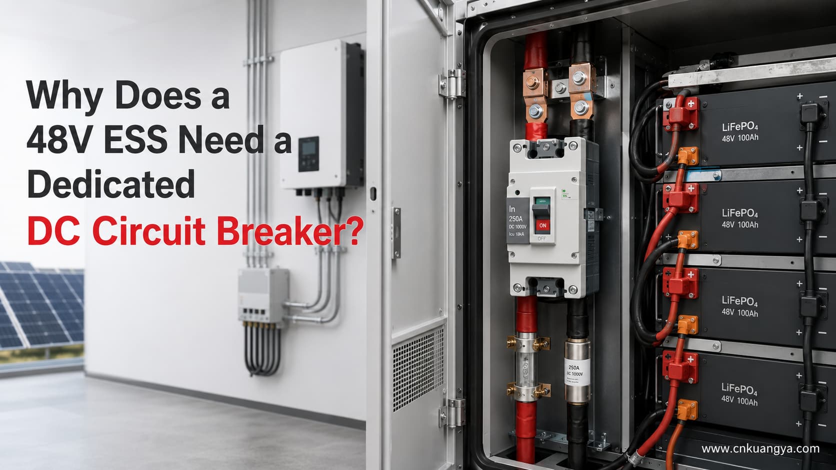
クイックアンサー: A 48V energy storage system may be classified as low voltage, but it can carry hundreds of amperes. A correctly selected 48V DCサーキットブレーカーが helps protect battery cables, busbars and inverter input circuits against overcurrent and short-circuit faults while providing a practical means of isolation. A battery management system (BMS), contactor, fuse and circuit breaker perform different functions; they should be coordinated rather than treated as interchangeable devices.
This article explains why “48V”does not mean “low risk,”what a DC breaker actually protects and which data must be checked before selecting a rating. For a broader overview, see our ESS向け直流遮断器選定ガイド(完全版).
Battery-side current can be estimated with:
DC current approximatelyoutput power / (battery voltage x inverter efficiency)
For example, a 10kW inverter operating at 48V with 95% efficiency draws approximately:
10,000 / (48 x 0.95) approximately219A
However, 48V is normally a nominal system description, not a fixed operating voltage. If the battery voltage falls to 40V, the same 10kW load at 95% efficiency may draw approximately 263A. The final calculation must therefore use the actual battery voltage range and consider continuous power, peak power, surge duration, charge current, discharge current and temperature derating.
A battery bank can deliver very high fault current. Depending on the system design, credible faults may include:
The protection design should limit damage and disconnect the affected circuit under defined fault conditions. It must also account for the energy available from every connected battery branch.
Some BMS designs include overcurrent or short-circuit detection and can command a contactor or electronic switch to open. That capability is important, but it does not automatically make the BMS a substitute for a properly coordinated branch overcurrent protective device.
The correct arrangement depends on the battery manufacturer, inverter instructions, applicable standards and the system fault study. In some ESS designs, a fuse and MCCB are used together rather than as alternatives.
Alternating current passes through a natural current zero every cycle. Direct current does not, so a DC arc can be more difficult to extinguish. An AC marking alone is not evidence that a breaker is suitable for a battery circuit.
Check the manufacturer’s declared:
Relevant requirements for low-voltage circuit breakers are covered by IEC 60947-2:2024. Equipment selection and erection must also follow the applicable installation rules and local regulations.
A circuit breaker is primarily selected to protect the circuit conductors and interrupt specified fault currents. Depending on its location, it may protect:
It does not directly manage individual cells or replace cell monitoring, thermal management, battery contactors or measures intended to mitigate thermal runaway. The protective device is normally installed close enough to the source to minimize the length of unprotected conductor, subject to the equipment instructions and system design.
Do not select a breaker using inverter power or battery ampere-hours alone. A preliminary engineering check should include:
The breaker should protect the conductor without nuisance tripping during legitimate operating peaks. Final settings require the actual equipment data and coordination study.
Preliminary engineering calculation
Estimate continuous charging and discharging currents, then keep the preliminary continuous design current separate from the discharge peak check. Calculations run only in your browser.
Charging current = charging power 脳 1000 梅 (minimum voltage 脳 charging efficiency). Discharging current uses the same relationship. Preliminary continuous design current = the higher continuous current 脳 design factor. Peak-check current = discharging current 脳 peak factor. Inputs: Calculated locally: The simplified charging estimate uses the entered minimum battery voltage. Actual charging current remains limited by the charger, battery, and BMS charging profile.Current estimate
Formulas and assumptions
It may be a candidate, but it is not an automatic choice. At 48V and 95% efficiency, a 10kW load is approximately 219A. At 40V, it can be approximately 263A. Battery discharge limits, inverter overload capability and transient duration can change the result further.
A 250A DC MCCB should only be considered after confirming:
Send us your battery voltage range, inverter model and current data if you want help checking whether a 250A model fits your application.
There is no universal answer. A 1-pole arrangement may be acceptable when the system design permits interruption of one conductor and all equipment requirements are satisfied. A 2-pole device may be required when both positive and negative conductors must be disconnected.
The decision depends on:
Do not select the pole count from nominal voltage alone.
Yes. An ESS normally carries current in both charge and discharge directions. Some DC breakers are polarity-sensitive, and not every device is declared suitable for bidirectional operation. Confirm the manufacturer’s documentation instead of assuming that a generic “DC”marking guarantees bidirectional use.
Provide the following information when requesting a recommendation:
It normally needs a coordinated means of overcurrent protection and isolation, but the exact arrangement may use a circuit breaker, fuse or a combination. Follow the battery and inverter instructions, the system fault study and applicable installation rules.
Not automatically. Some BMS units detect overcurrent and command a disconnect, but that function must be evaluated as part of the complete protection design. It does not by itself prove that branch conductors have a suitably rated fault-interruption device.
Only if the manufacturer explicitly provides a suitable DC rating and wiring instructions for the exact application. Do not infer DC capability from the AC rating.
Calculate current using minimum battery voltage and efficiency, then check continuous current, surge duration, conductor ampacity, trip curve, temperature derating and prospective fault current. Inverter wattage alone is insufficient.
Possibly, but not in every system. The current can exceed 250A at low battery voltage, and suitability also depends on cable protection, trip characteristics and DC breaking capacity.
The answer depends on the grounding arrangement and equipment instructions. Some systems interrupt one designated conductor; others require simultaneous disconnection of both conductors.
In some designs, yes. A fuse may provide high fault-current backup protection while the MCCB provides adjustable or resettable protection and isolation. The devices must be selectively coordinated.
A 48V ESS can carry enough current to overheat conductors and create severe DC fault energy. The correct solution is not simply to choose a breaker marked “48V”or match a 250A label to a 10kW inverter. A suitable 48V DCサーキットブレーカーが must be selected from the real voltage range, continuous and peak currents, conductor ampacity, grounding arrangement, current direction and prospective short-circuit current.
Need a technical selection check? Send Kuangya your battery voltage range, inverter model, maximum charge and discharge currents, peak-current duration, grounding arrangement and required certifications. We can help identify a suitable DC MCCB configuration for engineering review.

