Indirizzo
304 Nord Cardinale
St. Dorchester Center, MA 02124
Orario di lavoro
Da lunedì a venerdì: dalle 7.00 alle 19.00
Fine settimana: 10.00 - 17.00
Indirizzo
304 Nord Cardinale
St. Dorchester Center, MA 02124
Orario di lavoro
Da lunedì a venerdì: dalle 7.00 alle 19.00
Fine settimana: 10.00 - 17.00
By CNKuangya Senior Engineer

SPD: electrical systems become increasingly sophisticated and vulnerable to transient over voltages, the implementation of IEC 61643-31 compliant Surge Protective Devices (SPDs) has evolved from a recommended practice to an essential requirement. This comprehensive analysis examines the technical specifications, regulatory framework, and practical applications of IEC 61643-31 compliant SPDs, with particular emphasis on their deployment in residential and commercial distribution systems.
The IEC 61643-31 standard, published in 2018, represents a significant advancement in surge protection technology, specifically addressing the unique challenges of photovoltaic (PV) installations operating at DC voltages up to 1500V. However, the principles and technologies underlying this standard have broader implications for the entire spectrum of low-voltage surge protection applications.
IEC 61643-31:2018 establishes comprehensive requirements and test methods for surge protective devices specifically designed for photovoltaic installations. The standard addresses a critical gap in the protection landscape by extending coverage to DC systems operating at voltages up to 1500V DC, significantly higher than the 1000V AC limit of the traditional IEC 61643-11 standard. This extension was necessitated by the rapid evolution of PV technology, where higher DC voltages enable improved system efficiency and reduced conductor costs.
The standard applies to SPDs intended for protection against both indirect and direct effects of lightning strikes, as well as other transient overvoltages that can occur in photovoltaic systems. These transient events can originate from multiple sources including atmospheric discharges, switching operations in the utility grid, or internal system faults. The devices covered by this standard are designed for permanent connection to the DC side of photovoltaic generators and the DC input of inverters, requiring tools for connection and disconnection to ensure installation integrity and prevent unauthorized tampering.
The IEC 61643-31 standard establishes rigorous performance criteria that SPDs must satisfy to ensure reliable protection under diverse operating conditions. These specifications address the unique challenges of DC surge protection, which differs fundamentally from AC protection due to the absence of natural current zero-crossings that facilitate arc extinction in AC systems.
Voltage Ratings and Protection Levels:
The standard defines multiple voltage parameters that characterize SPD performance. The maximum continuous operating voltage (MCOV or Uc) represents the highest RMS or DC voltage that can be continuously applied to the SPD without causing degradation or failure. For PV applications, this value must be carefully selected based on the system’s maximum power point voltage under all operating conditions, including temperature variations and irradiance levels.
The voltage protection level (Up) indicates the maximum voltage that appears across the SPD terminals when conducting surge current. This parameter is critical for ensuring that protected equipment remains within its withstand capability during surge events. Lower protection levels provide superior equipment protection but may require more sophisticated and expensive SPD technologies.
Current Handling Capabilities:
IEC 61643-31 compliant SPDs must demonstrate the ability to handle multiple surge current waveforms that simulate real-world lightning and switching surge scenarios. The nominal discharge current (In) represents the peak current that the SPD can conduct multiple times without performance degradation, typically specified as an 8/20 μs waveform. The maximum discharge current (Imax) defines the upper limit of the SPD’s surge handling capability, beyond which permanent damage may occur.
For Type 1 SPDs intended for installation at the main power entry point, the standard requires testing with 10/350 μs current waveforms that simulate direct lightning strikes. These long-duration, high-energy pulses impose severe thermal and mechanical stress on SPD components, necessitating robust construction and high-quality materials.
SPDs complying with IEC 61643-31 must incorporate several design features that ensure safe and reliable operation throughout their service life. The standard mandates permanent connection methods that prevent accidental disconnection while allowing intentional removal using appropriate tools. This requirement addresses safety concerns related to arc flash hazards and ensures that protection remains in place during normal operation.
Thermal management represents another critical design consideration. SPDs must include provisions for heat dissipation under both normal operating conditions and during surge events. Inadequate thermal design can lead to premature aging of protective components, particularly metal oxide varistors (MOVs), which are sensitive to elevated temperatures. The standard requires testing under elevated ambient temperatures to verify thermal stability.
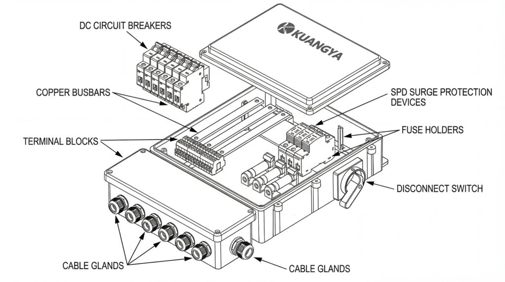
Visual and remote indication of SPD status is mandatory under IEC 61643-31. This feature enables maintenance personnel to quickly assess device condition without requiring electrical testing. Many modern SPDs incorporate both local LED indicators and remote signaling contacts that can interface with building management systems or supervisory control and data acquisition (SCADA) systems.
Modern IEC 61643-31 compliant SPDs employ multiple protection technologies, each offering distinct advantages for specific application requirements. Understanding these technologies enables engineers to select optimal solutions for their particular installation conditions.
Metal Oxide Varistors (MOVs):
MOVs represent the most widely deployed surge protection technology due to their excellent energy absorption capability, fast response time, and cost-effectiveness. These semiconductor devices exhibit highly nonlinear voltage-current characteristics, presenting high impedance at normal operating voltages and transitioning to low impedance when subjected to overvoltages. The transition occurs within nanoseconds, providing rapid clamping of transient voltages before they can propagate to sensitive equipment.
The performance of MOV-based SPDs depends critically on proper sizing and thermal management. Undersized MOVs may fail catastrophically under high-energy surge events, while oversized devices may exhibit excessive clamping voltages that reduce protection effectiveness. Temperature significantly affects MOV characteristics, with elevated temperatures reducing energy absorption capability and accelerating aging processes.
Gas Discharge Tubes (GDTs):
GDTs offer superior surge current handling capability and virtually unlimited service life when properly applied. These devices consist of electrodes sealed in a gas-filled ceramic or glass envelope. Under normal operating conditions, the gas provides excellent insulation, presenting extremely high impedance. When voltage across the electrodes exceeds the breakdown threshold, the gas ionizes rapidly, creating a low-impedance arc that diverts surge current to ground.
The primary limitation of GDTs is their relatively high sparkover voltage and finite response time, typically measured in microseconds. This characteristic makes standalone GDT protection unsuitable for sensitive electronic equipment that requires tighter voltage clamping. However, GDTs excel in applications requiring high surge current capability and are frequently combined with MOVs in hybrid SPD designs that leverage the advantages of both technologies.
Silicon Avalanche Diodes (SADs):
SADs provide the fastest response time and most precise voltage clamping of any surge protection technology, making them ideal for protecting highly sensitive electronic circuits. These solid-state devices enter avalanche breakdown at precisely defined voltages, offering excellent clamping characteristics and minimal voltage overshoot. However, their limited energy absorption capability restricts their use to secondary protection stages or low-energy surge environments.
Effective surge protection requires coordinated deployment of multiple SPD stages, each optimized for specific protection objectives. This layered approach, often termed the “zones of protection” concept, ensures that high-energy surges are progressively attenuated as they propagate through the electrical system, with each protection stage handling energy levels appropriate to its technology and location.
Type 1 SPDs (Class I):
These devices install at the main power entry point, typically at the service entrance or main distribution board. Type 1 SPDs must withstand direct lightning strikes, requiring robust construction and the ability to conduct 10/350 μs impulse currents. Their primary function is to prevent high-energy surges from entering the facility, thereby protecting downstream equipment and secondary SPD stages from catastrophic damage.
Type 2 SPDs (Class II):
Type 2 devices provide protection against switching surges and attenuated lightning surges at sub-distribution boards and branch circuits. These SPDs handle 8/20 μs impulse currents and offer lower voltage protection levels than Type 1 devices, making them suitable for protecting sensitive equipment. In many residential and commercial installations, Type 2 SPDs installed at the main distribution board provide adequate protection without requiring Type 1 devices.
Type 3 SPDs (Class III):
Type 3 SPDs install at the point of utilization, providing final protection for particularly sensitive equipment. These devices offer the lowest voltage protection levels but limited surge current capability, making them dependent on upstream Type 1 or Type 2 protection to prevent overload during high-energy surge events.
Selecting appropriate SPDs requires careful evaluation of multiple performance parameters and their relationship to installation conditions and protected equipment characteristics. Engineers must balance competing requirements including protection level, surge current capability, reliability, and cost to achieve optimal system performance.
The following table summarizes key technical parameters for different SPD types and their typical application contexts:
| Parametro | DOCUP di tipo 1 | DOCUP di tipo 2 | DOCUP di tipo 3 | Selection Consideration |
|---|---|---|---|---|
| Corrente di scarica nominale (In) | 15-25 kA (10/350 μs) | 20-40 kA (8/20 μs) | 5-10 kA (8/20 μs) | Higher values provide greater protection margin and extended service life |
| Corrente di scarica massima (Imax) | 25-100 kA (10/350 μs) | 40-120 kA (8/20 μs) | 10-20 kA (8/20 μs) | Must exceed worst-case surge current based on lightning risk assessment |
| Livello di protezione della tensione (su) | 2,5-4,0 kV | 1.5-2.5 kV | 0.8-1.5 kV | Lower values provide better equipment protection; must coordinate with equipment withstand voltage |
| Tempo di risposta | < 100 ns | < 25 ns | < 5 ns | Faster response reduces let-through energy; critical for sensitive electronics |
| Maximum Continuous Operating Voltage (Uc) | 1.1-1.45 × Un | 1.1-1.45 × Un | 1.1-1.3 × Un | Must accommodate temporary overvoltages without SPD activation |
| Posizione di installazione | Service entrance, main DB | Schede di sottodistribuzione | Point of use, socket outlets | Location determines exposure to surge energy and coordination requirements |
| Applicazioni tipiche | Buildings with external lightning protection, high exposure | Standard residential/commercial, moderate exposure | Sensitive equipment, data centers | Application dictates required protection level and surge current capability |
| Seguire l'interruzione della corrente | Must interrupt AC/DC follow current | Must interrupt AC/DC follow current | Typically not required for low-power circuits | Critical for DC applications where natural current zero-crossing is absent |
| Backup Protection | External overcurrent device rated 100-125 A | External overcurrent device rated 32-63 A | May use internal fusing | Ensures safe failure mode and prevents fire hazard |
The IEC 61643 series forms part of a comprehensive standards framework addressing all aspects of surge protection in low-voltage electrical installations. Understanding the relationships between these standards enables engineers to design compliant protection systems that meet regulatory requirements while providing effective equipment protection.
IEC 61643-11 establishes requirements for DOCUP in AC power systems up to 1000V, covering the vast majority of residential and commercial applications. This standard defines the three SPD types (Type 1, 2, and 3) based on their surge current handling capability and intended installation location. It specifies test procedures including voltage protection level measurement, nominal and maximum discharge current tests, temporary overvoltage withstand, and operating duty tests that simulate repeated surge exposure.
IEC 61643-12 provides guidance on the selection and application of SPDs in low-voltage power systems. This technical specification addresses risk assessment methodologies, coordination between multiple SPD stages, and integration with other protective devices including circuit breakers and residual current devices (RCDs). It references IEC 62305 (Lightning Protection Standard) for evaluating lightning risk and determining appropriate protection measures.
IEC 61643-21 and 61643-22 address surge protection for telecommunications and signaling networks, covering systems with nominal voltages up to 1000V AC and 1500V DC. These standards are particularly relevant for protecting data communication infrastructure, building automation systems, and industrial control networks that are increasingly integrated with power distribution systems.
IEC 61643-31 and 61643-32 specifically address photovoltaic installations, with 61643-31 covering AC-side protection and 61643-32 addressing DC-side protection. These standards recognize the unique challenges of PV systems, including higher DC voltages, the absence of natural current zero-crossings, and the potential for sustained fault currents that can lead to catastrophic SPD failure if not properly managed.
Beyond device-level standards, several installation standards mandate or recommend SPD deployment in various applications. IEC 60364-4-44 and IEC 60364-5-53, which form part of the comprehensive IEC 60364 series on electrical installations in buildings, establish requirements for protection against voltage disturbances and electromagnetic disturbances. The 2015 edition of these standards significantly strengthened SPD requirements, making them mandatory in many circumstances rather than merely recommended.
The standards require SPD installation at the origin of the installation (main distribution board) when the installation includes sensitive electronic equipment, which encompasses virtually all modern residential and commercial buildings. Additional SPD stages may be required based on risk assessment considering factors including lightning activity level, building height and exposure, presence of external lightning protection systems, and the value and sensitivity of equipment to be protected.
While IEC standards provide the international framework for surge protection, many countries and regions have adopted modified versions or supplementary requirements that reflect local conditions and regulatory philosophies. European countries typically adopt IEC standards as EN (European Norm) standards with minimal modification, ensuring harmonization across the European Union. However, specific installation requirements may vary based on national electrical codes and building regulations.
North American practice follows UL 1449 (Standard for Surge Protective Devices), which differs from IEC 61643 in several respects including voltage protection level measurement methodology, SPD type classification, and marking requirements. Engineers working on international projects must carefully navigate these differences to ensure compliance in all relevant jurisdictions.
Modern residential electrical installations face increasing surge protection challenges due to the proliferation of sensitive electronic equipment, integration of renewable energy systems, and the growing adoption of smart home technologies. A typical residential SPD installation at the main distribution board provides comprehensive protection for all downstream circuits and connected equipment.
System Architecture:
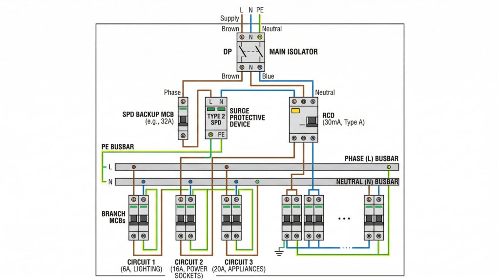
The residential distribution board serves as the central hub for power distribution and protection. In a standard single-phase installation, the main switch or circuit breaker connects to the utility supply, followed by the SPD installation between the main switch and the branch circuit protective devices. This location ensures that the SPD can intercept surges at the point of entry, before they propagate to individual circuits and connected equipment.
The SPD connects to all current-carrying conductors (phase, neutral) and the main earthing terminal. Proper earthing is critical for SPD effectiveness, as the device must provide a low-impedance path for surge current to flow to ground. The earth conductor should be as short and straight as possible, with a maximum length of 0.5 meters recommended to minimize inductance that could increase voltage drop during surge events.
Selezione dei componenti:
For most residential applications, a Type 2 SPD with nominal discharge current (In) of 20-40 kA (8/20 μs) provides adequate protection. The maximum continuous operating voltage (Uc) must be selected based on the nominal system voltage and expected temporary overvoltages. For 230V single-phase systems, a Uc of 275-320V is typical, providing margin for voltage fluctuations while ensuring the SPD does not activate during normal operating conditions.
The voltage protection level (Up) should not exceed the impulse withstand voltage of the most sensitive equipment in the installation. Modern electronic equipment typically has impulse withstand capability of 2.5-4 kV, making SPDs with Up ≤ 1.5 kV suitable for comprehensive protection. Lower protection levels provide superior equipment protection but may increase SPD cost and require more frequent replacement due to the increased stress on protective components.
Installation Considerations:
Proper installation technique significantly impacts SPD performance and reliability. The connection conductors between the distribution board busbars and the SPD terminals should be sized according to the SPD manufacturer’s specifications, typically 6-10 mm² for residential applications. Oversized conductors do not improve protection and may increase installation cost and complexity, while undersized conductors can create voltage drop during surge events that reduces protection effectiveness.
Visual indication of SPD status enables homeowners or maintenance personnel to quickly identify failed devices requiring replacement. Many modern SPDs incorporate colored indicators (green for operational, red for failed) along with mechanical flags that remain visible even during power outages. Some advanced models offer remote signaling contacts that can interface with home automation systems, enabling proactive maintenance alerts.
Commercial installations typically involve more complex electrical systems with higher power demands, three-phase supply, and multiple distribution levels. These factors necessitate more sophisticated surge protection strategies that coordinate multiple SPD stages and integrate with other protective devices.
Three-Phase System Protection:
Commercial buildings commonly utilize three-phase electrical distribution to supply large loads and provide balanced power distribution. SPD protection in three-phase systems requires devices that connect to all three phase conductors, the neutral (if present), and the protective earth. The configuration depends on the system earthing arrangement (TN-S, TN-C-S, TT, or IT) and the presence or absence of a neutral conductor.
In TN-S systems, which feature separate protective earth and neutral conductors throughout the installation, the SPD typically employs a 3+1 configuration with separate protection modules for each phase-to-earth path and the neutral-to-earth path. This arrangement provides independent protection for each conductor while allowing individual module replacement if one fails, reducing maintenance cost and downtime.
TT systems, common in rural areas and some European countries, present unique challenges for SPD application due to the higher earth resistance of the installation earthing system. In these installations, the SPD must coordinate with the residual current device (RCD) at the origin of the installation to ensure that SPD operation does not cause nuisance tripping. Specialized SPDs with current-limiting components or time-delayed response may be necessary to achieve proper coordination.
Multi-Level Protection Strategy:
Large commercial buildings often implement multiple SPD stages to provide comprehensive protection throughout the facility. Type 1 or Type 1+2 combined SPDs install at the main distribution board, providing primary protection against high-energy surges entering from the utility supply. Type 2 SPDs at sub-distribution boards offer secondary protection for specific building zones or floors, reducing the voltage protection level and providing backup protection if the primary SPD fails or is bypassed by surges induced in internal wiring.
Coordination between SPD stages requires careful attention to energy coordination (ensuring upstream devices can handle energy not diverted by downstream devices) and voltage coordination (ensuring the voltage protection level decreases at each successive stage). Minimum separation distances between SPD stages, typically 10-15 meters of cable length, help ensure proper energy sharing and prevent premature failure of downstream devices.
Integration with Building Management Systems:
Modern commercial buildings increasingly integrate surge protection monitoring into building management systems (BMS) or energy management systems (EMS). SPDs with remote signaling contacts provide dry contact closures that indicate device status, enabling real-time monitoring and automated maintenance alerts. This integration supports predictive maintenance strategies that reduce downtime and extend equipment life by ensuring failed SPDs are promptly replaced.
Advanced SPD monitoring systems may also track surge event frequency and magnitude, providing valuable data for assessing lightning risk and evaluating the effectiveness of protection measures. This information can inform decisions regarding additional protection stages, lightning protection system upgrades, or equipment hardening measures for particularly vulnerable assets.
Example 1: Small Office Building (Single-Phase, 230V)
A two-story office building with 20 workstations, server room, and HVAC equipment requires surge protection at the main distribution board. The electrical system consists of a 100A main switch, 30mA RCD for socket outlet circuits, and individual MCBs for lighting, power, and HVAC circuits.
SPD Selection: Type 2 SPD, 1-pole + N configuration, In = 40 kA (8/20 μs), Imax = 80 kA, Up ≤ 1.5 kV, Uc = 275V
Installazione: SPD installs between the main switch and RCD, with connections to the phase busbar, neutral busbar, and main earthing terminal. A 32A Type C circuit breaker provides backup protection for the SPD. Total installation time: approximately 1 hour for a qualified electrician.
Cost-Benefit Analysis: SPD cost approximately $150-250, installation labor $100-150. Protected equipment value exceeds $50,000 (computers, servers, HVAC controls). Single surge event could cause equipment damage exceeding $10,000, making SPD installation highly cost-effective with payback period less than one year in moderate lightning risk areas.
Example 2: Retail Store (Three-Phase, 400V)
A large retail store with extensive lighting, refrigeration equipment, point-of-sale systems, and security equipment requires comprehensive surge protection. The electrical system includes a 250A main switch, three-phase distribution to HVAC and refrigeration equipment, and single-phase circuits for lighting and power outlets.
SPD Selection: Type 1+2 combined SPD, 3+1 configuration (3 phase + neutral), In = 25 kA (10/350 μs) / 50 kA (8/20 μs), Imax = 100 kA, Up ≤ 2.0 kV, Uc = 320V per phase
Installazione: SPD installs immediately downstream of the main switch, with short, direct connections to phase busbars, neutral busbar, and main earthing terminal. A 125A circuit breaker provides backup protection. Additional Type 2 SPDs install at sub-distribution boards serving particularly sensitive equipment (POS systems, security).
Considerazioni speciali: Refrigeration equipment is particularly vulnerable to surge damage due to electronic controls and variable-speed compressor drives. SPD protection prevents costly equipment failures and product loss due to refrigeration system downtime. The retail environment also requires minimal installation disruption, making the compact, DIN-rail mounted SPD format ideal for this application.
The following table provides a comprehensive comparison of SPD applications in residential and commercial distribution systems:
| Aspetto | Residential Application | Commercial Application | Engineering Rationale |
|---|---|---|---|
| Tensione del sistema | Single-phase 120/230V | Three-phase 208/400/480V | Commercial systems use higher voltages for efficiency and load capacity |
| Typical SPD Type | Tipo 2 (Classe II) | Type 1+2 or coordinated Type 1 & Type 2 | Commercial buildings face higher lightning exposure and require robust primary protection |
| SPD Configuration | 1+1 (L+N) or 1-pole + N | 3+1 (3L+N) or 3+0 (delta systems) | Configuration matches system topology and earthing arrangement |
| Corrente di scarica nominale | 20-40 kA (8/20 μs) | 25-50 kA (10/350 μs for Type 1) | Higher values accommodate greater lightning exposure and larger facility size |
| Protection Levels | Single stage at main DB | Multi-stage: main DB + sub-DBs | Commercial installations require layered protection due to facility size and equipment value |
| Posizione di installazione | Main distribution board only | Main DB + sub-distribution boards | Distributed protection reduces voltage stress on long cable runs |
| Backup Protection | 32-63A MCB or fuse | 63-125A MCB or fuse | Larger backup protection accommodates higher SPD current ratings |
| Indicazione di stato | Visual indicator (LED/flag) | Visual + remote signaling contacts | Commercial applications benefit from BMS integration for proactive maintenance |
| Coordination with RCD | Must not cause nuisance tripping | Critical in TT systems; may require selective RCDs | Ensures SPD operation doesn’t compromise ground fault protection |
| Earth Connection | Single earth bar connection | May require separate earth busbar | Commercial systems often have more complex earthing arrangements |
| Typical Protected Equipment | Computers, TVs, appliances, smart home devices | Servers, POS systems, HVAC, refrigeration, security systems | Commercial equipment is often more expensive and business-critical |
| Costo dell'installazione | $200-400 (device + labor) | $800-3,000+ depending on size/complexity | Commercial installations require larger devices and more complex integration |
| Requisiti di manutenzione | Ispezione visiva annuale | Quarterly inspection + remote monitoring | Commercial applications justify more intensive maintenance due to higher equipment value |
| Regulatory Drivers | IEC 60364-5-53, local building codes | IEC 60364-5-53, insurance requirements, industry standards | Commercial installations face more stringent regulatory and insurance requirements |
| Expected Service Life | 10-15 years in moderate exposure | 5-10 years in high exposure environments | Service life depends on surge frequency and magnitude |
Below is a comprehensive installation diagram showing proper SPD integration in both residential and commercial distribution boards:
Diagram Key Features:
Installation Best Practices:
Q1: What is the difference between IEC 61643-31 and IEC 61643-11 standards?
IEC 61643-31 specifically addresses surge protective devices for photovoltaic installations operating at DC voltages up to 1500V, while IEC 61643-11 covers SPDs for AC power systems up to 1000V. The key distinction lies in the voltage range and the unique challenges of DC surge protection, particularly the absence of natural current zero-crossings that facilitate arc extinction in AC systems. IEC 61643-31 includes additional requirements for DC arc interruption capability and testing under conditions representative of PV system operation, including high ambient temperatures and sustained fault current scenarios. However, the fundamental protection principles and many test methodologies are similar between the two standards, and manufacturers often leverage common technologies (MOVs, GDTs) across both AC and DC SPD product lines.
Q2: How do I determine the appropriate SPD type for my installation?
SPD selection depends on multiple factors including installation location, lightning risk level, system earthing arrangement, and protected equipment sensitivity. For residential installations in moderate lightning risk areas, a Type 2 SPD at the main distribution board typically provides adequate protection. Commercial installations, particularly those with external lightning protection systems or in high lightning risk areas, should employ Type 1 or combined Type 1+2 SPDs at the main distribution board. Buildings taller than 20 meters, structures with metal roofs, or facilities housing particularly sensitive or valuable equipment may require multi-stage protection with additional Type 2 or Type 3 SPDs at sub-distribution boards or points of utilization. Consulting IEC 61643-12 and IEC 62305-2 provides detailed risk assessment methodologies to support systematic SPD selection.
Q3: Can SPDs prevent all surge damage?
SPDs significantly reduce surge-related equipment damage but cannot provide absolute protection under all circumstances. Extremely high-energy direct lightning strikes may exceed SPD capacity, particularly if the device is undersized or has degraded due to previous surge exposure. Additionally, surges can couple into equipment through paths not protected by the SPD, such as data communication lines, antenna connections, or metallic piping systems. Comprehensive protection requires a systems approach that includes SPDs on all conductive paths entering the facility, proper earthing and bonding of metallic systems, and coordination with lightning protection systems where present. Equipment with particularly high sensitivity or value may warrant additional point-of-use protection beyond distribution board SPDs.
Q4: How often should SPDs be inspected and replaced?
SPD inspection frequency depends on lightning exposure level and the criticality of protected equipment. Residential installations in moderate lightning risk areas typically require annual visual inspection to verify status indicator condition and check for signs of physical damage or overheating. Commercial installations should undergo quarterly inspections, particularly in high lightning risk regions or where equipment downtime has significant financial consequences. SPDs should be replaced immediately upon failure indication (red status indicator or open remote contact) or after known high-energy surge events such as nearby lightning strikes. Even if the status indicator shows operational condition, SPDs should be replaced every 10-15 years as a precautionary measure, as protective components can degrade over time even without obvious failure.
Q5: Why is proper earthing so critical for SPD performance?
The SPD diverts surge current to earth, making the earthing system the ultimate destination for surge energy. High earthing impedance limits the current that can flow through the SPD, reducing its effectiveness and potentially causing dangerous voltage rise at the earthing system. The connection between the SPD and the main earthing terminal should be as short and direct as possible, ideally less than 0.5 meters total length, using conductors with adequate cross-section (minimum 6 mm² for residential, 10-16 mm² for commercial applications). Bends and loops in the earth conductor should be avoided as they increase inductance, which becomes significant at the high frequencies present in lightning surges. In installations with poor earthing systems (high earth resistance), improving the earthing system may be necessary before SPD installation to ensure effective protection.
Q6: Can I install an SPD myself, or do I need a qualified electrician?
SPD installation requires working within the main distribution board on live electrical systems, presenting serious shock and arc flash hazards. In most jurisdictions, this work must be performed by licensed electricians in accordance with local electrical codes and regulations. Improper installation can result in ineffective protection, damage to the SPD or other distribution board components, or serious safety hazards including fire and electric shock. Even for those with electrical knowledge, professional installation is strongly recommended to ensure proper device selection, correct connection configuration, adequate backup protection, and compliance with all applicable standards and regulations. The modest cost of professional installation is insignificant compared to the potential consequences of improper installation.
Q7: Do I need SPD protection if I have a surge protector power strip?
Surge protector power strips provide point-of-use protection but offer inferior performance compared to properly installed distribution board SPDs. Power strips typically employ small MOVs with limited energy absorption capability, making them suitable only for minor surges from local switching events. They cannot effectively protect against high-energy surges from lightning strikes or utility system disturbances. Additionally, power strips protect only equipment plugged into them, leaving hardwired appliances (HVAC systems, water heaters, garage door openers) completely unprotected. Distribution board SPDs provide whole-facility protection for all connected equipment and can handle much higher surge energies. The optimal approach combines distribution board SPDs for primary protection with quality power strips for sensitive electronics, providing layered protection that addresses both high-energy and low-level surge threats.
Q8: How does SPD protection interact with renewable energy systems?
Photovoltaic systems, wind turbines, and battery storage systems introduce additional surge protection challenges due to their exposure to lightning (rooftop or elevated mounting), DC electrical systems, and bidirectional power flow. IEC 61643-31 and 61643-32 specifically address PV system protection, requiring SPDs on both the DC side (between PV array and inverter) and AC side (between inverter and distribution board). The DC-side SPDs must be rated for the system’s maximum open-circuit voltage, which can exceed 1000V in large commercial installations, and must be capable of interrupting DC fault current without relying on natural current zero-crossings. Battery storage systems require similar DC-side protection, with SPDs rated for the battery system voltage. Proper protection system design requires coordination between AC and DC SPDs, integration with the facility’s main distribution board protection, and consideration of earthing and bonding requirements for the renewable energy equipment.
The implementation of IEC 61643-31 compliant surge protective devices represents a critical component of modern electrical system design, providing essential protection against the increasingly prevalent threat of transient overvoltages. As electrical systems become more complex and dependent on sensitive electronic equipment, the consequences of inadequate surge protection continue to escalate, making SPD installation not merely a recommended practice but an essential requirement for reliable system operation.
For residential applications, the installation of Type 2 SPDs at the main distribution board provides cost-effective whole-home protection that safeguards valuable electronics, appliances, and smart home systems. The modest investment in SPD protection, typically $200-400 including installation, offers compelling return on investment by preventing equipment damage that could cost thousands of dollars to repair or replace.
Commercial installations warrant more sophisticated protection strategies that may include Type 1 primary protection, multiple SPD stages, and integration with building management systems for proactive maintenance. The higher equipment values and business continuity requirements of commercial facilities justify these additional measures, which provide robust protection while supporting predictive maintenance approaches that minimize downtime.
As we advance into an era of increasing electrification, renewable energy integration, and smart building technologies, the role of surge protection will only grow in importance. Engineers, facility managers, and building owners who prioritize proper SPD selection, installation, and maintenance position their facilities for reliable, efficient operation in the face of inevitable surge events. The standards framework established by IEC 61643-31 and related standards provides the technical foundation for these protection systems, ensuring that properly designed installations deliver effective protection throughout their service life.
Informazioni sull'autore:
This technical analysis was prepared by CNKuangya, a senior electrical engineer specializing in power distribution systems, surge protection, and renewable energy integration. With extensive experience in residential, commercial, and industrial applications, CNKuangya provides expert guidance on electrical system design, protection coordination, and compliance with international standards.
Riferimenti: