WengYang Industrial Zone Yueqing Wenzhou 325000
Work Hours
Monday to Friday: 7AM - 7PM
Weekend: 10AM - 5PM
WengYang Industrial Zone Yueqing Wenzhou 325000
Work Hours
Monday to Friday: 7AM - 7PM
Weekend: 10AM - 5PM
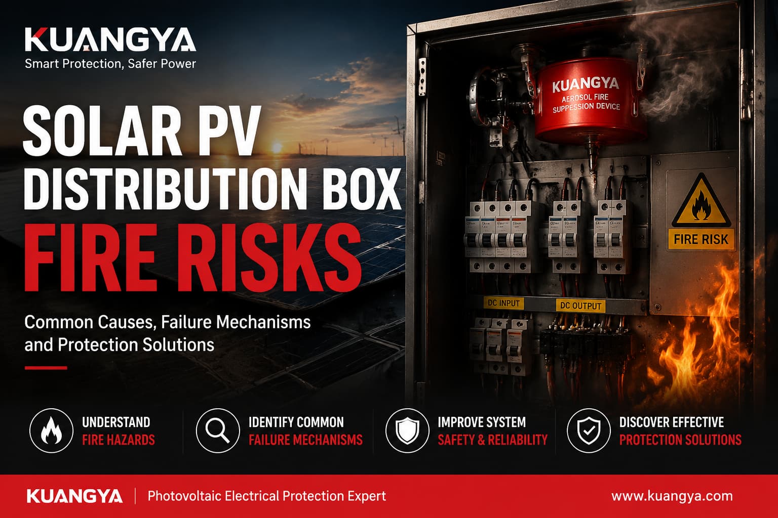
Solar PV Distribution Box Fire Risks are a critical concern in modern photovoltaic systems. Although most PV installations are equipped with multiple electrical protection devices such as gPV fuses, circuit breakers, isolators and surge protective devices (SPDs), fire incidents can still occur inside distribution-level equipment under certain operating conditions.
According to IEA PVPS research reports, a significant proportion of photovoltaic system failures are related to electrical and installation-level issues rather than major equipment breakdowns.
Field experience from PV system maintenance shows that these incidents are rarely caused by complete system failure. Instead, they are often linked to localized electrical issues within distribution boxes, such as connection degradation, insulation stress, or component aging.
In many documented inspection cases, engineers have found that early-stage thermal abnormalities inside PV distribution boxes can develop gradually without triggering immediate protection devices. This makes routine maintenance and environmental monitoring an important part of system reliability.
This article is based on field observations from solar PV maintenance practices and focuses on common failure mechanisms found in distribution-level electrical equipment. It reflects issues frequently identified during real-world inspections rather than purely theoretical risks.
Photovoltaic system design and electrical safety are governed by international IEC photovoltaic system safety standards standards, which define requirements for installation practices, equipment coordination, and system-level protection in PV applications.
Understanding Solar PV Distribution Box Fire Risks is essential for system designers and maintenance engineers.
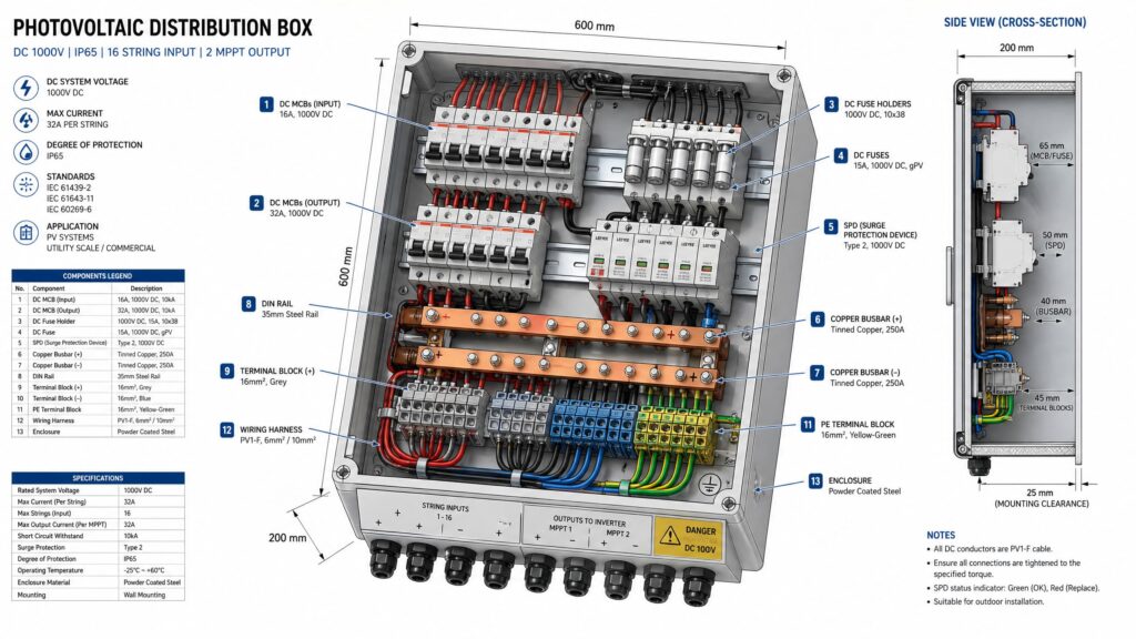
PV distribution boxes serve as central connection points in photovoltaic systems. They integrate multiple input strings, protection devices, and output circuits within a single enclosed structure.
Unlike conventional electrical systems, PV installations generate electricity whenever sufficient sunlight is available. This means:
Distribution boxes are often installed in rooftop environments or remote solar farms where maintenance access may be limited. As a result, small internal issues may remain undetected for long periods before developing into serious electrical hazards.
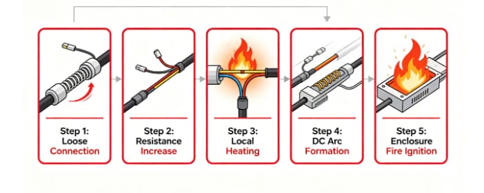
One of the most frequently observed issues in PV distribution boxes is poor or deteriorating electrical connections.
A connection may initially be installed correctly but gradually loosen over time due to thermal expansion, vibration, material aging, or improper torque during installation.
As contact resistance increases, localized heating begins to develop. Importantly, this process is often gradual and may not immediately trigger protective devices.
Loose connections are one of the most common contributors to Solar PV Distribution Box Fire Risks in field operations.
During a routine maintenance inspection at a commercial rooftop solar installation, technicians were performing infrared thermal imaging on several DC distribution boxes. The plant had been operating for more than three years without any reported electrical faults, and all protective devices appeared to be functioning normally.
However, thermal imaging revealed that one cable termination inside a distribution box was operating at a significantly higher temperature than neighboring connections carrying similar current levels.
While most terminals were within normal operating temperature ranges, the affected connection exceeded 90°C under comparable load conditions.
No fuse had operated.
No circuit breaker had tripped.
The monitoring system had not generated any alarms.
After isolating the system and inspecting the enclosure, technicians discovered that the connection had gradually loosened over time. The resulting increase in contact resistance had created continuous localized heating.
Although the system was still operational, nearby insulation materials had already begun to discolor due to prolonged exposure to elevated temperatures.
Had the issue remained undetected, continued heating could have led to insulation failure and eventually created ignition conditions inside the enclosure.
Situations like this are frequently reported during PV maintenance activities and highlight an important reality: many electrical fire risks develop slowly and silently rather than through sudden failure events.
In many cases, overheating at connection points is related to improper current interruption or protection coordination. A properly selected gPV fuse for photovoltaic systems can help reduce the risk of excessive fault current propagation inside distribution boxes.
Learn more about: solar DC gPV fuse protection solutions
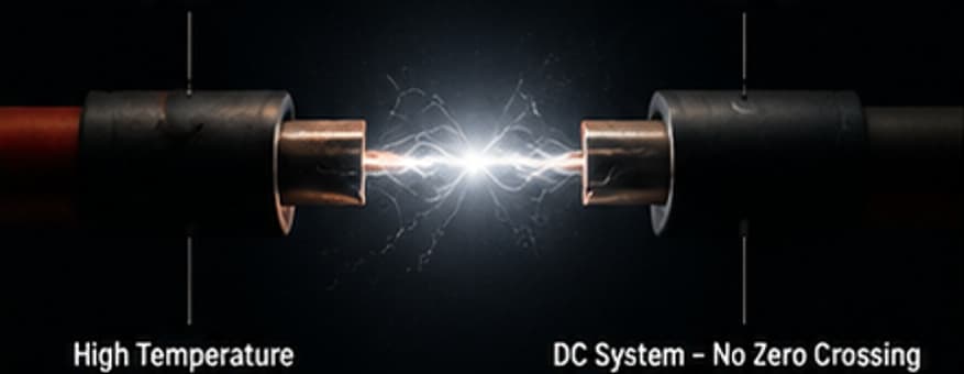
An arc occurs when current bridges a gap between conductors through air or damaged insulation. In DC systems, this condition is particularly hazardous because direct current does not naturally pass through a zero-crossing point as alternating current does. This allows arcs to persist for longer durations and reach extremely high temperatures.
Common causes include:
From a system design perspective, DC arc fault risks are recognized in international photovoltaic standards such as IEC 62548, which defines installation requirements and electrical safety practices for PV array systems.
In practical field operations, engineers have observed that DC arc faults are most frequently detected at cable termination points, connector interfaces, and areas with compromised insulation, where minor contact defects can gradually evolve into sustained arcing conditions.In practical field operations, engineers have observed that DC arc faults are most frequently detected at cable termination points, connector interfaces, and areas with compromised insulation, where minor contact defects can gradually evolve into sustained arcing conditions.
Industry reports and case studies published by PV Magazine indicate that DC arc faults are most commonly found at cable termination points and connector interfaces, where installation quality and mechanical stress play a critical role in long-term reliability.
A critical misunderstanding in electrical fire prevention is assuming that all dangerous conditions will trigger protective devices.
In reality, not all overheating events involve excessive current.
For example:
In these cases, fuses and circuit breakers may not operate because electrical current remains within acceptable limits.
As a result, temperature rise can continue unnoticed until insulation materials begin to degrade.
| Protection Device | What It Protects Against | What It Cannot Detect | Fire Risk Still Possible? |
|---|---|---|---|
| gPV Fuse | Overcurrent / short circuit | Localized overheating | Yes |
| Circuit Breaker | Overload / short circuit | High resistance heating | Yes |
| SPD | Voltage surges | Internal thermal aging | Yes |
| Monitoring System | Electrical anomalies | Mechanical loosening | Yes |
| Isolation Switch | Manual disconnection | Thermal degradation | Yes |
Thermal imaging inspections in PV systems frequently reveal early-stage warning signs of potential failures.
Common findings include:
These indicators often appear long before any operational failure occurs. Identifying them early is one of the most effective ways to prevent electrical fires.
| Inspection Item | Method | Recommended Frequency | Risk Level if Ignored |
|---|---|---|---|
| Terminal tightness | Torque check | Annually | High |
| Thermal hotspots | Infrared imaging | 6–12 months | High |
| SPD status indicator | Visual inspection | Quarterly | Medium |
| Cable insulation condition | Visual inspection | Annually | High |
| Dust accumulation | Visual inspection / cleaning | 6 months | Medium |
| Connector condition | Manual inspection | Annually | High |
Fuses play an essential role in photovoltaic protection systems, particularly gPV fuses designed for DC applications.
However, certain risks are associated with improper fuse selection or installation:
In many maintenance cases, overheating is found at the fuse holder rather than inside the fuse element itself. This indicates that connection quality is just as important as fuse specification.
Understanding how different protective devices behave under fault conditions is essential for proper system design. For a detailed technical comparison between fuses and surge protection devices in photovoltaic systems, see:
DC Fuse vs DC SPD in Solar PV Systems: Key Differences and Applications
Surge protective devices are designed to protect PV systems from transient overvoltage events caused by lightning or switching surges.
Although SPDs are highly reliable, they have a finite service life. Repeated surge events gradually degrade internal components.
Field inspections often reveal:
While modern SPDs typically include thermal disconnection mechanisms, neglected maintenance can reduce overall system protection effectiveness.SPD degradation is another factor that can increase Solar PV Distribution Box Fire Risks over long-term operation.
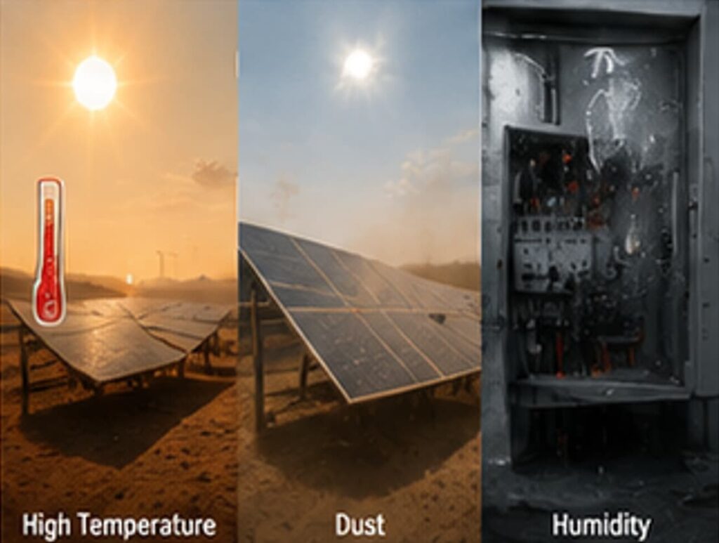
Environmental conditions have a significant impact on the long-term reliability of PV distribution boxes, especially in outdoor installations where equipment is continuously exposed to thermal cycling, dust, and humidity variations.
Unlike controlled indoor electrical environments, PV distribution boxes often operate under harsh and unstable conditions. Over time, these environmental stresses do not cause immediate failure, but gradually accelerate insulation aging, increase connection resistance, and reduce overall system stability.
In many rooftop solar installations, enclosure temperatures can rise significantly due to direct sunlight exposure and limited heat dissipation.
During field inspections in hot climate regions such as the Middle East and Southeast Asia, engineers frequently observe internal cabinet temperatures exceeding 60°C during peak daytime operation.
Although components are typically rated for high temperatures, prolonged thermal stress accelerates insulation aging and can contribute to loosening of electrical connections over time.
Dust accumulation is another common issue, particularly in desert or industrial environments.
Maintenance teams often report fine dust layers forming around terminal blocks and ventilation openings. While dust alone may not cause immediate failure, it reduces heat dissipation efficiency and can increase the risk of surface tracking when combined with humidity.
In several field inspections, heavily dust-contaminated enclosures have shown uneven temperature distribution, with localized hot spots forming around connection points.
Moisture ingress or long-term condensation is a critical factor in coastal and high-humidity regions.
Field engineers often observe corrosion traces on terminals and busbars inside enclosures installed near coastal solar farms. Over time, corrosion increases contact resistance, which can lead to localized heating under normal operating current.
Even when the system continues to operate normally, insulation materials may gradually degrade due to repeated exposure to moisture cycles.
Ventilation limitations inside compact PV distribution boxes can further amplify thermal stress.
In real-world installations, especially where enclosures are densely packed with protection devices, heat buildup is often uneven. Components located near the top of the cabinet tend to operate at higher temperatures due to natural convection patterns.
If airflow is restricted or cable routing blocks internal circulation paths, localized overheating can develop even under normal load conditions.
These environmental factors do not usually cause immediate system failure. Instead, they gradually create conditions that increase electrical resistance, accelerate material aging, and amplify existing installation or design weaknesses.
In many real-world cases, environmental stress is not the direct cause of fire incidents, but a contributing factor that pushes already vulnerable connections or components toward failure.
Many PV system issues are ultimately linked to installation or maintenance practices.
Common contributing factors include:
Even high-quality components cannot compensate for poor installation practices.
| Failure Type | Typical Location | Mechanism | Detectable Early Sign |
|---|---|---|---|
| Loose connections | Cable terminals / busbar joints | Increased contact resistance leading to heat buildup | Thermal hotspot, discoloration |
| Arc faults | Connectors / damaged cables | Electrical discharge through air gap | Burning smell, intermittent fault |
| Insulation aging | Cable insulation layers | Thermal + UV degradation over time | Cracking, color change |
| SPD degradation | Surge protection modules | Repeated surge exposure reduces performance | Status indicator change |
| Poor crimping | Connector joints | High resistance at termination point | Localized heating |
Field experience consistently shows that electrical fires rarely occur without warning.
Common early indicators include:
Recognizing these signs early significantly reduces fire risk in PV installations.
Modern PV systems are designed with multiple protective layers, including:
However, no protection system can eliminate all possible failure modes.
Certain conditions such as:
may not immediately trigger protective devices.
For this reason, system designers increasingly consider additional safety layers beyond conventional electrical protection.
In recent years, localized fire suppression systems installed inside electrical enclosures have been evaluated as an additional safety measure in photovoltaic systems.
Unlike conventional building-level fire protection, these systems are designed to act directly within the enclosure where ignition occurs.
When a fire develops inside a confined electrical space, rapid intervention can significantly reduce damage and system downtime.
Such systems are not intended to replace electrical protection devices but to complement them as part of a layered safety approach.
| Cabinet Area / Risk Zone | Recommended Placement | Reason for Placement | Installation Consideration |
|---|---|---|---|
| Upper internal space of cabinet | Ceiling/top inside enclosure | Hot air and smoke naturally rise to the top during early fire stage | Ensure unobstructed aerosol dispersion path |
| Cable termination zone | Side wall facing cable entry points | Most overheating and arc faults occur at terminals | Avoid direct obstruction from cables |
| Busbar / distribution area | Central upper-mid section | High current concentration area with potential hotspot formation | Maintain safe distance from conductive parts |
| Fuse and breaker compartment | Adjacent upper side wall | Fuse holders often develop resistance heating | Do not block maintenance access |
| Enclosure air circulation zone | Upper rear corner (if available space exists) | Helps rapid gas distribution throughout enclosure | Avoid mounting near ventilation openings that cause leakage |
An effective photovoltaic fire protection strategy typically includes multiple layers:
1. System Design Stage
2. Installation Stage
3. Electrical Protection Devices
4. Preventive Maintenance
5. Localized Fire Suppression
Each layer contributes to reducing overall system risk.
In addition to traditional electrical protection devices, some modern photovoltaic installations are now considering additional layers of protection inside electrical enclosures. This includes localized suppression technologies designed for cabinet-level fire risks.
Learn more about KUANGYA electrical cabinet fire suppression solutions
Fire risks in solar PV distribution boxes rarely originate from a single catastrophic failure. Instead, they often develop gradually through a combination of electrical, mechanical, and environmental factors.Addressing Solar PV Distribution Box Fire Risks requires a layered approach combining design, installation and maintenance.
Loose connections, arc faults, improper fuse installation, SPD degradation, and environmental stress all contribute to long-term risk accumulation.
The most effective approach to fire prevention is not reliance on a single protective device, but the combination of sound engineering design, high-quality components, proper installation practices, regular maintenance, and multiple layers of protection.
Q1: How do I identify a potential fire risk in my PV distribution box before it happens?
Q2: Does my solar PV system definitely need both an SPD and an RCBO?
Q3: Which international standards should my PV distribution box comply with?
Q4: How often is professional maintenance required for a commercial PV system?
Answer: Professional maintenance should be conducted at least every 6 to 12 months. For large-scale commercial arrays, we recommend quarterly inspections, specifically focusing on the electrical connections within the combiner and distribution boxes, where current density is highest.
