WengYang Industrial Zone Yueqing Wenzhou 325000
Work Hours
Monday to Friday: 7AM - 7PM
Weekend: 10AM - 5PM
WengYang Industrial Zone Yueqing Wenzhou 325000
Work Hours
Monday to Friday: 7AM - 7PM
Weekend: 10AM - 5PM

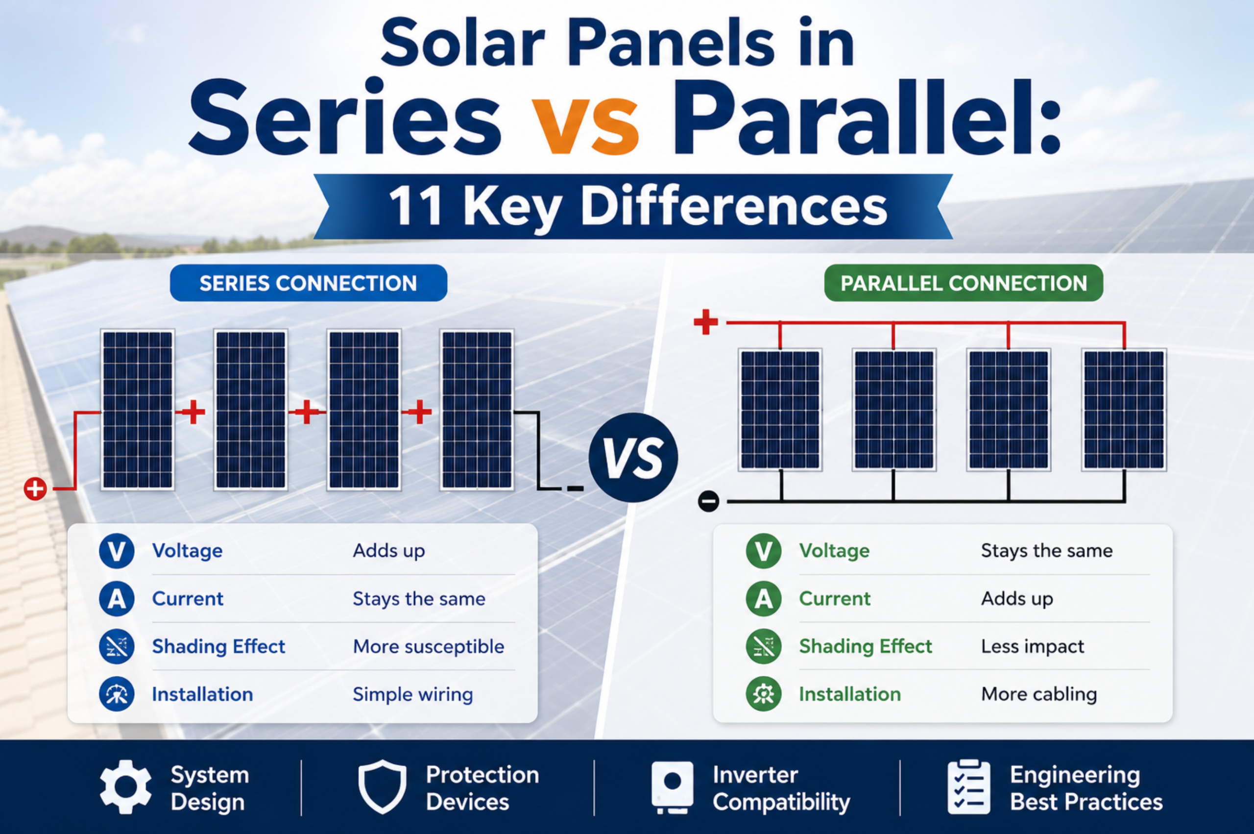
When designing a photovoltaic system, one of the first electrical decisions is how the solar modules should be connected.
Should you wire the solar panels in series, where the voltage increases?
Should you wire the solar panels in parallel, where the current increases?
Or should you use a series-parallel configuration to achieve the voltage and current required by the inverter?
The answer affects much more than total system power. The connection method influences:
A PV module produces direct-current electricity, and multiple modules are connected into strings and arrays to achieve the voltage and current required by the system. NREL photovoltaic modeling likewise treats module and array behavior through series and parallel electrical connections. de explains solar panels in series vs parallel from both a practical and engineering perspective. It also shows how wiring configuration affects overcurrent protection, combiner boxes, surge protective devices, DC isolators, and inverter selection.
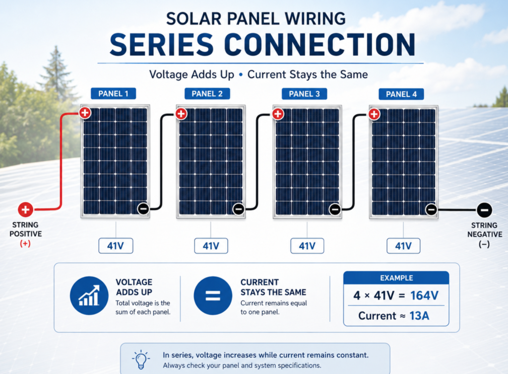
The basic rule is simple:
Series connections increase voltage. Parallel connections increase current.
For identical solar panels:
Voltage adds together.
Current remains approximately equal to the current of one module.
Example:
4 panels, each rated:
Series result:
Approximate array power:
164 V × 13 A = 2,132 W
Voltage remains approximately equal to one module.
Current adds together.
Using the same four modules:
Approximate array power:
41 V × 52 A = 2,132 W
The theoretical power is similar, but the voltage, current, cable requirements, protection devices, and inverter operating conditions are very different.
| Design Factor | Series Connection | Parallel Connection |
|---|---|---|
| Voltage | Adds together | Remains similar to one string |
| Current | Remains similar to one string | Adds together |
| Cable current | Lower | Higher |
| Voltage drop concern | Often lower for equal power and cable assumptions | Higher current can increase losses |
| Inverter voltage | Must stay below maximum DC input voltage | Must remain inside MPPT operating range |
| Input current | Usually lower | Can become high |
| String fuse requirement | Depends on number of parallel strings and design | Often more relevant with multiple parallel strings |
| Combiner box | Not normally needed for one simple string | Common when combining multiple strings |
| Shading behavior | Can affect string current and I-V curve | Depends on string arrangement and MPPT architecture |
| Main design risk | Excessive DC voltage | Excessive DC current |
| Common application | PV strings | Combining multiple strings |
The real design decision is therefore not simply:
“Which wiring method produces more power?”
For the same number of identical modules under the same conditions, the theoretical total power does not increase simply because the modules are rearranged.
The correct question is:
Which configuration allows the PV array to operate safely inside the electrical limits of the inverter and the rest of the DC system?
A series connection creates one continuous electrical path through multiple solar modules.
The positive terminal of one panel is connected to the negative terminal of the next.
A simplified arrangement looks like this:
PV Module 1        PV Module 2        PV Module 3        PV Module 4

(-)      (+)------(-)      (+)------(-)      (+)------(-)      (+)

|                                                                  |
Negative Output                                           Positive Output
The modules become one PV string.
When identical modules are connected in series:
Total voltage ≈ Sum of individual module voltages
String current ≈ Current of one module
For four identical modules:
Module Vmp = 41 V
Module Imp = 13 A

Series Vmp = 41 + 41 + 41 + 41
           = 164 V

Series Imp = 13 A
Series-connected PV modules are widely used because a higher DC voltage can deliver a given amount of power at a lower current than a low-voltage configuration.
Because conductor losses are related to current and resistance, system voltage and current are important factors in cable design. However, actual cable sizing must still consider conductor length, allowable voltage drop, installation conditions, temperature, ampacity requirements, and applicable electrical standards.
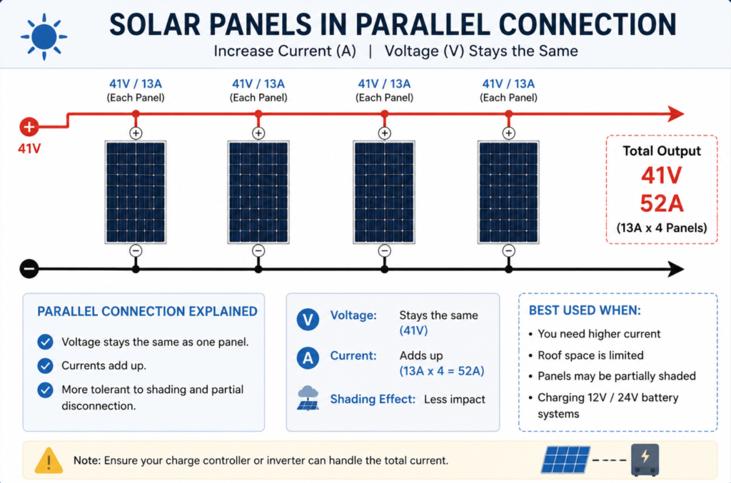
In a parallel connection:
A simplified arrangement looks like this:
                +---- PV String 1 ----+
                |                     |
Positive Bus ---+---- PV String 2 ----+--- Output
                |                     |
                +---- PV String 3 ----+

Negative Bus --- Common negative connection
For identical strings connected in parallel:
Voltage remains approximately equal to the voltage of one string.
Current is approximately the sum of the string currents.
Example:
Three identical strings:
String Vmp = 500 V
String Imp = 13 A
Parallel result:
Array Vmp ≈ 500 V

Array Imp ≈ 13 + 13 + 13
          = 39 A
This is the basic principle behind many PV combiner boxes.
Multiple PV strings enter the combiner box and are connected to a common DC output through appropriately designed protection and switching components.
Understanding the basic voltage and current rules is only the beginning.
The following differences determine whether a PV system will operate efficiently, safely, and within the electrical limits of its equipment.
The most important difference between solar panels in series vs parallel is voltage.
Module voltages add together.
For ten modules with:
Vmp = 42 V
Voc = 50 V
The approximate string values are:
String Vmp = 42 × 10 = 420 V
String Voc = 50 × 10 = 500 V
If several identical ten-module strings are connected in parallel:
String Vmp = 420 V
String Voc = 500 V
The array voltage remains approximately:
Vmp ≈ 420 V
Voc ≈ 500 V
The current increases instead.
This distinction is critical because every inverter has defined DC voltage limits.
Exceeding the maximum permitted DC input voltage can damage equipment or create an unsafe operating condition.
Series and parallel configurations affect current in the opposite way.
The current does not add as modules are placed in series.
Ten identical modules rated at 13 A do not produce 130 A simply because they are connected in one series string.
The string current remains approximately the operating current of the series circuit.
Current adds when matched strings are connected in parallel.
For example:
1 string = 13 A
2 strings = 26 A
4 strings = 52 A
8 strings = 104 A
This increasing current affects:
A system can therefore remain safely below its maximum voltage while still exceeding the current capability of an inverter input or electrical protection device.
The inverter is one of the most important factors when choosing between series and parallel wiring.
A PV inverter usually specifies parameters such as:
A PV array must satisfy all relevant electrical limits.
The string may exceed:
Maximum inverter DC input voltage
This risk is particularly important during low-temperature conditions because PV module open-circuit voltage can vary with temperature.
The operating voltage may fall below:
The inverter may fail to start or may not operate as intended.
The combined current may exceed:
Therefore, the number of modules in series and the number of strings in parallel must be calculated separately.
Suppose a solar module has the following electrical values:
| Parameter | Value |
|---|---|
| Maximum Power | 550 W |
| Vmp | 41.5 V |
| Imp | 13.25 A |
| Voc | 49.8 V |
| Isc | 14.0 A |
Now connect 20 identical modules in series.
String Vmp = 41.5 × 20
           = 830 V
String Voc = 49.8 × 20
           = 996 V
String Imp ≈ 13.25 A
String Isc ≈ 14.0 A
20 × 550 W = 11,000 W
The string therefore has approximately:
However, the design must not stop at multiplying the nameplate Voc.
Actual maximum design voltage must account for the module’s specified voltage-temperature behavior and the minimum design temperature applicable to the project.
Modern PV array design requirements also extend beyond simple arithmetic to DC wiring, protection devices, switching, and earthing. IEC 62548-1:2023, together with its 2025 amendment, addresses PV array design requirements in these areas. . How to Calculate Solar Panels in Parallel
Now suppose we connect four identical 20-module strings in parallel.
Each string provides approximately:
Vmp = 830 V
Imp = 13.25 A
Voc = 996 V
Isc = 14.0 A
For four identical parallel strings:
Vmp ≈ 830 V
Voc ≈ 996 V
Array Imp = 13.25 × 4
          = 53 A
Array Isc = 14 × 4
          = 56 A
20 modules × 4 strings × 550 W
= 44,000 W
The array is therefore approximately:
44 kWp
But the system’s current-carrying components must now be designed for the combined parallel current and applicable design requirements.
That can affect:
This is one of the most important PV string design calculations.
The answer cannot be based only on the inverter’s nominal DC voltage.
You need at least:
A simplified concept is:
Maximum Number of Modules in Series

≈ Maximum Permitted DC Voltage
  ÷ Maximum Corrected Module Voc
However, the maximum corrected Voc should be calculated using the module manufacturer’s data and the project’s minimum design temperature.
Assume:
Module Voc at reference conditions = 50 V
Corrected maximum Voc at low temperature = 55 V
Inverter maximum input voltage = 1,100 V
Then:
1,100 ÷ 55 = 20 modules
Therefore:
20 modules may be the mathematical upper limit in this simplified example.
But a professional design should normally avoid treating a simplified division as the complete design process.
The engineer must verify:
The current IEC 60364-7-712:2025 edition includes requirements associated with PV power supply installations and replaced the previous 2017 edition. . How Many Strings Can Be Connected in Parallel?
The maximum number of parallel strings is often controlled by current.
Suppose:
String Imp = 13 A
String Isc = 14 A

Inverter maximum input current per MPPT = 52 A
A simple operating-current comparison gives:
52 ÷ 13 = 4 strings
But that does not automatically prove that four strings are acceptable.
You must also check:
This distinction matters because:
Maximum operating input current and maximum permitted short-circuit current are not always the same specification.
Never design only from one number on the inverter datasheet.
This is where many simplified online explanations become misleading.
You may see statements such as:
“Parallel is always better under shading.”
That is too simplistic.
The real behavior depends on:
NREL testing and modeling have shown that partial shading can produce nonlinear power loss and alter PV array operating points. Bypass diodes can conduct when a protected section of a module is sufficiently affected, changing the module voltage and the overall I-V curve. Happens in a Series String?
Modules in a series circuit share the same string current.
A shaded or mismatched section can therefore affect the operating behavior of the complete string.
Bypass diodes can reduce some effects by allowing current to bypass affected cell groups, but this also changes the available module voltage.
The result can be:
One affected parallel string does not necessarily force all other strings to produce the same current.
However, parallel operation still depends on:
Therefore, parallel wiring is not a universal cure for shading.
A better design principle is:
Group modules with similar orientation, irradiance, and operating conditions whenever possible, and use the inverter’s MPPT architecture correctly.
Technically, different modules can sometimes be electrically connected, but mixing significantly different modules is generally undesirable unless the complete electrical behavior has been properly evaluated.
In a series circuit, current compatibility is especially important.
Consider:
Vmp = 40 V
Imp = 13 A
Vmp = 42 V
Imp = 10 A
The lower-current module can constrain the operating behavior of the series circuit.
The total string does not simply operate as if every module can independently produce its own maximum-power current.
Mismatch may reduce output and complicate MPPT behavior.
For professional installations, designers should carefully evaluate differences in:
Parallel connections create a different challenge.
Parallel strings should have compatible operating voltages.
Connecting strings with significantly different voltage characteristics to the same electrical node or MPPT input can result in poor operating compatibility.
For example:
String A Vmp = 500 V
String B Vmp = 350 V
Simply connecting these strings in parallel does not allow each string to independently operate at its preferred maximum-power voltage on a single common input.
For this reason, different:
may be better assigned to separate MPPT inputs where the inverter architecture permits.
This is one of the most important safety questions in PV array design.
The answer is:
Not every single PV circuit automatically requires the same fuse arrangement.
However, when multiple strings are connected in parallel, reverse current from other strings can become an important design consideration.
Imagine one string develops a fault.
Other parallel strings may be capable of feeding current toward the faulted circuit.
The protection design must therefore consider:
This is where gPV fuse links for photovoltaic string protection are commonly used in photovoltaic systems.
A properly selected PV fuse is intended to provide overcurrent protection for the relevant DC circuit under defined fault conditions.
It should not be confused with an SPD.
Protects against specified overcurrent conditions.
Limits transient overvoltage and diverts surge current.
Provides switching and overcurrent protection according to its design and rating.
Provides a means of isolation and switching according to its intended function.
These products perform different jobs.
One should not be used as a substitute for another.
A PV combiner box becomes especially relevant when multiple PV strings must be combined into a common output.
A simplified architecture is:
String 1 ── Fuse ──┐
                   │
String 2 ── Fuse ──┤
                   │
String 3 ── Fuse ──┤── DC Bus ── SPD ── DC Output ── Inverter
                   │
String 4 ── Fuse ──┘
Depending on the system design, a combiner box may contain:
The exact configuration depends on the project.
A combiner box should not simply be described as a “box that connects wires together.”
It is part of the DC electrical architecture.
Its components must be selected according to:
For a given amount of power:
P = V × I
A higher-voltage system can transmit the same power at a lower current.
Example:
Power = 10,000 W
Voltage = 100 V

Current = 100 A
Power = 10,000 W
Voltage = 500 V

Current = 20 A
This does not mean that “higher voltage always means smaller cable” in every situation.
Cable selection still depends on:
But the current difference is one reason high-voltage PV strings are widely used in larger systems.
Large commercial and utility-scale PV plants often use higher DC system voltages than small residential systems.
The logic remains the same.
Creates:
Creates:
However, higher system voltage places stricter requirements on every DC component.
For a 1500V DC architecture, relevant equipment may include:
The voltage rating of the complete system is not determined by one component.
Every component in the relevant circuit must be appropriate for its actual electrical duty.
There is no universal answer.
Connecting the same matched solar panels in series instead of parallel does not magically create additional module energy.
Efficiency depends on the complete system.
Important variables include:
Most medium and large PV installations do not choose only “series” or only “parallel.”
They use both.
Modules are connected in series to form strings.
Multiple strings are then connected in parallel.
Consider:
Total modules:
20 × 8 = 160 modules
Total nominal power:
160 × 550 W
= 88,000 W
= 88 kWp
If each module has:
Vmp = 41.5 V
Imp = 13.25 A
Then one string is approximately:
Vmp = 41.5 × 20
    = 830 V

Imp = 13.25 A
Eight strings in parallel produce approximately:
Array Vmp = 830 V

Array Imp = 13.25 × 8
          = 106 A
This is a classic series-parallel PV array.
The series connection creates the required voltage.
The parallel connection creates the required current and total capacity.
PV arrays can be exposed to transient overvoltages associated with lightning effects and other electrical disturbances.
Depending on the project design, DC SPDs may be installed at locations such as:
The correct surge protection architecture depends on:
A DC SPD does not replace:
Likewise, a fuse does not provide surge protection.
The devices should be selected as part of a coordinated protection system.
A practical system can be visualized as:
SOLAR MODULES
     │
     ▼
SERIES-CONNECTED PV STRING
     │
     ▼
gPV STRING FUSE
     │
     ▼
PV COMBINER BOX
     │
     ├── DC SPD
     │
     ├── BUSBAR
     │
     └── DC SWITCHING / PROTECTION
     │
     ▼
DC CABLE
     │
     ▼
DC ISOLATOR / CIRCUIT PROTECTION
     │
     ▼
INVERTER
     │
     ▼
AC PROTECTION
     │
     ▼
GRID / LOAD
Not every project uses exactly this architecture.
For example:
The architecture must therefore be based on the actual equipment and project.
This can push the maximum string voltage above the inverter or equipment rating.
Always calculate maximum expected Voc, not only nominal operating voltage.
A parallel array may remain below the inverter voltage limit while exceeding its current limit.
Check both.
PV module voltage changes with operating conditions.
Use manufacturer data and the correct project design conditions.
Different string lengths can create incompatible operating voltages.
Do not assume that any two strings can simply be connected in parallel.
Two strings that fit the inverter’s total power rating may still be unsuitable for the same MPPT input.
Read the inverter’s input architecture carefully.
Shading behavior is more complex.
It depends on module bypass diodes, MPPT operation, array layout, and shading patterns. NREL research has documented significant mismatch effects and nonlinear performance under partial shading. Mistake 7: Combining Strings Without Evaluating Overcurrent Protection
Multiple parallel strings can change available fault current.
Evaluate string protection requirements.
A device rated for AC service should not automatically be assumed suitable for PV DC service.
Verify the complete application rating.
The array, fuse, combiner box, SPD, isolator, cable, and inverter form one electrical system.
A good design coordinates all of them.
| Situation | Main Design Direction |
|---|---|
| Need higher DC voltage | Add modules in series, within voltage limits |
| Need more array power without increasing string voltage | Add parallel strings, within current limits |
| Long DC cable distance | Evaluate higher-voltage architecture and cable losses |
| Inverter voltage too low | More modules may be required in series |
| Inverter maximum voltage nearly reached | Do not add more modules without calculation |
| Inverter input current nearly reached | Do not add more parallel strings without calculation |
| Multiple strings entering one DC output | Evaluate combiner box and protection |
| Parallel strings can feed a faulted string | Evaluate string overcurrent protection |
| Lightning or surge exposure | Evaluate coordinated DC surge protection |
| Maintenance isolation required | Select appropriate DC switching/isolation equipment |
Before finalizing a solar array, verify:
PV array design requirements cover more than module connection alone. The IEC 62548-1 framework includes DC array wiring, electrical protection, switching, and earthing considerations, while IEC 60364-7-712 addresses PV electrical installations. requently Asked Questions
Neither is universally better.
Series connections increase voltage.
Parallel connections increase current.
The correct arrangement depends on:
Most larger systems use a combination of series and parallel connections.
For the same matched modules under the same operating conditions, changing the wiring configuration alone does not create extra module power.
For example:
Series:
160 V × 10 A = 1,600 W

Parallel:
40 V × 40 A = 1,600 W
The voltage and current are different, but the theoretical total power is similar.
Actual system energy production may differ because of:
The voltages of the modules add together.
For four identical 50 V open-circuit modules:
4 × 50 V = 200 V Voc
The actual design must also consider voltage changes with temperature.
The currents of matched parallel strings add together.
For four 13 A strings:
4 × 13 A = 52 A
The cables, protection devices, and inverter input must be suitable for the resulting current.
It may be physically possible, but mismatched current and voltage characteristics can reduce performance and create design complications.
Matched modules are generally easier to design and operate predictably.
This should not be done casually.
Different string lengths usually produce different operating voltages.
Strings connected to the same common input should be electrically compatible with that input and with each other.
Not always.
Small systems may connect a limited number of strings directly to an inverter designed with multiple string inputs.
A combiner box becomes more relevant when several strings must be combined and managed through a common DC output.
Series connections allow the system to build sufficient voltage for the inverter while keeping string current relatively low.
The maximum number of modules must still be limited by the maximum permitted system and inverter voltage.
Not necessarily, but it can significantly affect string behavior.
The result depends on:
Partial shading can create nonlinear losses rather than a simple one-panel-equals-one-panel-loss relationship. Is Parallel Better for Shading?
Not automatically.
Parallel architecture can change how shading affects the array, but performance depends on the complete electrical design.
The number of MPPT inputs, string configuration, bypass diodes, and shading pattern all matter.
The maximum number depends primarily on:
Never determine string length from panel wattage alone.
The practical limit depends on:
Multiple parallel strings may require string overcurrent protection depending on the array configuration, available reverse current, module specifications, and applicable design requirements.
The complete system should be evaluated rather than applying one rule to every installation.
A PV string is typically a group of modules connected in series.
A PV array can include one or more strings, often connected through series-parallel arrangements.
No.
A fuse and an SPD perform different functions.
A fuse addresses specified overcurrent conditions.
A surge protective device limits transient overvoltage and diverts surge current.
A complete PV system may require both.
Understanding solar panels in series vs parallel is essential for designing a safe and efficient photovoltaic system.
The basic electrical rule is straightforward:
Series increases voltage. Parallel increases current.
But professional PV system design requires much more than this basic rule.
The designer must coordinate:
The most common architecture for commercial and utility-scale photovoltaic systems is a series-parallel array.
Modules are connected in series to create the required DC voltage.
Multiple strings are then connected in parallel to achieve the required system capacity.
As the number of parallel strings increases, electrical protection becomes increasingly important.
A complete PV DC protection architecture may include:
PV modules → PV strings → gPV fuses → combiner box → DC SPD → DC circuit protection or isolation → inverter
The goal is not simply to connect as many solar panels as possible.
The goal is to create a PV array in which every component operates within its electrical limits and contributes to a coordinated protection system.
KUANGYA provides electrical protection solutions for photovoltaic DC systems, including gPV fuses, DC surge protective devices, circuit protection products, and components for PV combiner box applications. Project-based product selection and OEM support are available for distributors, EPC contractors, electrical panel manufacturers, and solar equipment companies.
For PV protection component selection, provide the system voltage, string configuration, current requirements, and application details so that the protection solution can be evaluated according to the actual project conditions.

