Address
304 North Cardinal
St. Dorchester Center, MA 02124
Work Hours
Monday to Friday: 7AM - 7PM
Weekend: 10AM - 5PM
Address
304 North Cardinal
St. Dorchester Center, MA 02124
Work Hours
Monday to Friday: 7AM - 7PM
Weekend: 10AM - 5PM

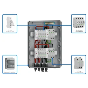
In a solar photovoltaic (PV) system, the combiner box plays a central role in consolidating power and ensuring safety. It’s a junction box where the output of multiple solar strings are connected in parallel, combining their current before sending it to the inverter. More importantly, it houses the critical overcurrent protection devices (fuses or circuit breakers) that protect the system’s wiring and components from potentially dangerous faults.
Properly sizing your PV combiner box and its internal components is not just a best practice—it’s a fundamental requirement for a safe, reliable, and code-compliant installation. An undersized component can lead to fire hazards, while an oversized one may fail to provide adequate protection.
This guide will walk you through the essential steps for matching your combiner box’s voltage and current ratings to your specific solar array, with a focus on the requirements outlined in the National Electrical Code (NEC). We will cover:

For any PV installation in the United States, NEC Article 690 is the ultimate authority. This section of the code is specifically dedicated to solar PV systems, addressing the unique characteristics and potential hazards of DC power generation. It provides the framework for everything from wiring and grounding to disconnecting means and overcurrent protection. Adhering to Article 690 is essential for ensuring your system is safe and will pass inspection.
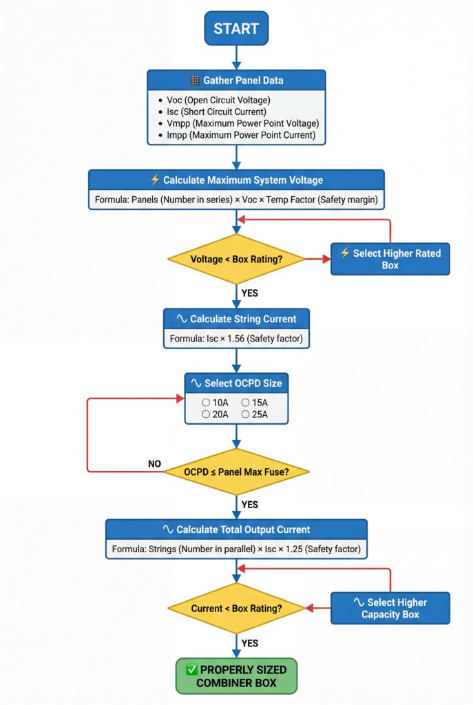
The first and most important parameter to determine is the maximum system voltage. All components in a circuit, from the wires to the fuses and the combiner box itself, must have a voltage rating equal to or greater than the maximum voltage they might experience.
In a PV system, the maximum voltage is determined by the number of modules in a series string and their open-circuit voltage (Voc), found on the module’s datasheet. However, voltage is inversely proportional to temperature; a solar panel’s voltage is highest on the coldest possible day. NEC requires you to calculate the maximum voltage for the lowest expected ambient temperature at your site.
How to Calculate Maximum System Voltage:
Corrected Voc = Voc × [1 + (Lowest Temp °C - 25°C) × (Voc Temp Coefficient %/°C)]Max System Voltage = Corrected Voc × Number of Modules in SeriesExample:
48.5V × [1 + (-10 - 25) × (-0.0028)] = 48.5V × [1 + (-35 × -0.0028)] = 48.5V × 1.098 = 53.25V53.25V × 12 = 639VIn this case, the system requires a combiner box, fuses, and breakers rated for at least 639V. Therefore, you would select components from a standard 1000V DC class, as 600V components would be insufficient.
After determining the voltage rating, the next step is to size the overcurrent protection devices (OCPDs), which are typically fuses. The primary purpose of string fuses is to protect against reverse current. A fault in one string can cause other strings to back-feed into it, creating a dangerous overcurrent condition.
Per NEC 690.9, string-level fusing is required whenever you have three or more strings in parallel. With only two strings, the reverse current potential is not high enough to exceed the module’s fuse rating, so fuses are not required by code (though they are still sometimes used as a disconnecting means).
How to Size String Fuses:
The NEC requires that the fuse be rated to handle continuous duty and potential irradiance spikes. This is accomplished by multiplying the module’s Short-Circuit Current (Isc) by a factor of 1.56.
1.25 × 1.25 = 1.56Fuse Rating Formula: Minimum Fuse Rating ≥ Module Isc × 1.56
After calculating this minimum, you select the next standard fuse size up.
Crucial Limitation: Maximum Series Fuse Rating\
Every solar module has a “Maximum Series Fuse Rating” listed on its datasheet. This value is an absolute limit. Your calculated fuse size must not exceed this rating. If it does, your system design is flawed, typically meaning your chosen module cannot be used with that many strings in parallel.
Example:
10.5A × 1.56 = 16.38ABased on this calculation, you would choose the next standard size up, which is a 20A fuse. Since 20A is equal to the module’s maximum series fuse rating, this is a valid selection. If the calculation had resulted in 21A, you would not be able to use a 25A fuse, and the design would need to be re-evaluated.
Protection coordination ensures that in the event of a fault, the correct OCPD opens first. For a fault within a single string, you want the individual string fuse to blow, isolating only that string without taking the entire array offline. The main OCPD at the combiner box output should only trip if there is a major fault on the main conductors leading to the inverter.
This is achieved by ensuring the downstream device has a lower rating than the upstream device.
| Component | Purpose | Sizing Rule of Thumb | NEC Reference |
|---|---|---|---|
| String Fuse | Protects individual strings from reverse current faults from other strings. | Isc × 1.56 (and must be ≤ Module Max Fuse Rating) | 690.9(A) |
| Main Combiner OCPD | Protects the main output wire from the combiner box to the inverter. | Sum of all string fuse ratings, rounded down to the nearest standard breaker size. Or (Total Isc × 1.25) and select the next standard OCPD size up. | 690.9(A) & 240.4 |
Do I need fuses for only two parallel strings?\
No. According to NEC 690.9, overcurrent protection is only required when there are three or more strings in parallel. With two strings, the maximum fault current that one string can source to the other is limited to the Isc of one string, which is below the module’s maximum fuse rating.
Can I use AC-rated fuses or breakers for DC circuits?\
No, you must use components specifically rated for DC circuits. DC arcs are much more difficult to extinguish than AC arcs. An AC-rated device will likely fail to safely interrupt a DC fault, leading to a significant fire and safety hazard.
What happens if I install the wrong size fuse?
Why is the 1.56 multiplier used for sizing?\
It’s a combined safety factor required by the NEC. It consists of two separate 1.25 multipliers: one to account for the fact that solar circuits are considered “continuous loads” (running at max current for more than 3 hours), and a second to account for irradiance levels that can exceed standard test conditions, causing current to rise temporarily above the rated Isc. (1.25 x 1.25 = 1.56).
What is a module’s “Maximum Series Fuse Rating”?\
This is a safety rating determined by the module manufacturer and certified by UL. It specifies the maximum current the module can withstand without being damaged when subjected to a reverse current. You must never install a fuse or OCPD rated higher than this value.
Matching a PV combiner box’s current and voltage ratings is a systematic process guided by engineering principles and the strict safety standards of the NEC. The core takeaways are:
By following these guidelines, you can ensure your solar array’s combiner box is sized safely, reliably, and professionally, forming a robust foundation for your entire PV system.
