WengYang Industrial Zone Yueqing Wenzhou 325000
Work Hours
Monday to Friday: 7AM - 7PM
Weekend: 10AM - 5PM
WengYang Industrial Zone Yueqing Wenzhou 325000
Work Hours
Monday to Friday: 7AM - 7PM
Weekend: 10AM - 5PM
Updated: · Reading time: ~18–22 min
Selecting the correct Surge Protective Device (SPD) is among the highest-ROI decisions in LV distribution, PV/ESS, EV charging, and industrial automation. This guide compiles standards-driven criteria (IEC/UL/NEC), placement rules, and BOM tips for both AC and DC systems. See the reference tables and sources at the end.
Unplanned downtime often costs USD 1–5M/hour; severe cases approach USD 300k/min. Surges from lightning/switching are predictable & engineerable; coordinated SPDs clamp high-energy impulses and protect PLCs/VFDs/IT.
U.S. detection networks record tens to hundreds of millions of lightning events annually; Florida often leads in density, Texas in totals. Use geography-aware specs (see §8) to justify higher Iimp/In ratings.
IEC 61643 defines performance & waveforms; UL 1449 lists safety/compliance for North America; NEC 2023 Article 242 mandates use in several contexts.
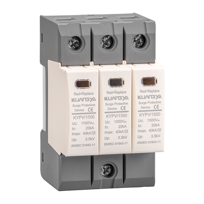
Type 1: 10/350 μs (Iimp) · Type 2: 8/20 μs (In/Imax) · Type 3: Combination (Uoc). PV/DC: IEC 61643-31 ≤1500 VDC.
UL listing for permanently connected SPDs; 4th Ed. (2016) refined markings.
Choose the type by exposure & board hierarchy; coordinate residual voltage (Up) across stages.
Test: 10/350 μs (Iimp). Install at service entrance when LPS/overhead.
Test: 8/20 μs (In/Imax). Sub-boards backbone protection.
Test: Combination (Uoc). Close to sensitive loads (PLCs, VFDs, IT).
Hybrid Type 1+2 = high energy + low residual. Selectors: AC · DC
AC side (IEC 61643-11 / UL 1449): choose Type 1/2/3 by exposure and board hierarchy, then size Uc, In/Imax, Up. DC side (IEC 61643-31): PV arrays up to 1500 VDC with different temperature, polarity and reverse-current behaviors vs. AC devices.
In modern BOS, PV combiner boxes often integrate Type 2 DC SPD, gPV fuses and DC disconnects—reducing enclosure count and simplifying field work.

This cascade mirrors IEC 60364-5-53 selection/erection principles and common manufacturer guidance.
See also: PV Combiner Boxes · High-Voltage gPV Fuses
Lightning exposure is not uniform. U.S. lightning reports routinely cite 90–240+ million events annually (in-cloud + CG) depending on methodology. Texas often leads total counts while Florida frequently leads density. For wind farms and tall infrastructure, stroke counts per site can exceed thousands.
For budgeting, use county-level maps from NOAA/NCEI or annual reports from Vaisala/AEM to justify Iimp/In choices and site placement.
Copy these rows into your spec sheets as a starting point.
| SPD Type | Primary Test | Key Ratings | Typical Location | Notes |
|---|---|---|---|---|
| Type 1 | 10/350 μs (Iimp) | Uc, Iimp, Up | Service entrance / MSB | Partial direct lightning current |
| Type 2 | 8/20 μs (In/Imax) | Uc, In/Imax, Up | Sub-distribution boards | Backbone protection |
| Type 3 | Combination (Uoc) | Uc, Uoc, Up | Near sensitive loads | Final clamp, coordinate with Type 2 |
| Parameter | Why it matters | Typical pitfalls |
|---|---|---|
| Uc (MCOV) | Must exceed worst-case continuous system voltage | Choosing too close to nominal → thermal stress & early end-of-life |
| Iimp / In / Imax | Match expected surge environment | Under-rating at service entrance; misusing Type 2 where Type 1 is needed |
| Up | Determines residual stress on insulation/electronics | Not coordinating Up across stages → equal-level protection |
| SCCR / Backup OCPD | Safety & selectivity | Mismatch with available fault current; ignoring vendor backup device tables |
| Pole count & Earthing | TN/TT/IT change module set and N-PE needs | Missing N-PE on TT; miswiring PEN in TN-C |
| Environment & Mounting | Temperature, altitude, IP/NEMA; conductor routing | Long lead lengths; sharp bends increase inductance (raise terminal Up) |
Global erection rules reference: IEC 60364-5-53.
The 2023 NEC (NFPA 70) strengthens SPD use in several contexts (e.g., whole-home protection at dwellings, fire pump controllers). Article 242 covers overvoltage protection for ≤1000 V installations; always match UL 1449 listing and installation location.
Reference: NFPA 70 (NEC) · UL 1449 explainer
If you have external LPS or overhead service, Type 1 (or 1+2) is the standard approach to handle partial direct lightning current. Underground-fed buildings sometimes justify robust Type 2, but assess risk (lightning density, entry routes) and local code.
UL 1449 is a listing/safety standard; IEC 61643 defines performance tests and types. Many data sheets display both. The 4th Edition of UL 1449 (2016) standardized newer markings and requirements.
In order: Uc (right, not low) → Iimp/In/Imax (enough) → Up (as low as coordination allows) → SCCR/backup → maintenance features.
Put budget at the service entrance (Type 1 or 1+2), then add Type 2/3 later. This blocks catastrophic energy from penetrating deep into the facility.
High-density corridors (e.g., Gulf Coast, Central Florida) justify higher Iimp/In and tighter Up targets. Use NCEI/Vaisala/AEM maps to quantify baseline flash densities for AHJ or insurance discussions.