WengYang Industrial Zone Yueqing Wenzhou 325000
Work Hours
Monday to Friday: 7AM - 7PM
Weekend: 10AM - 5PM
WengYang Industrial Zone Yueqing Wenzhou 325000
Work Hours
Monday to Friday: 7AM - 7PM
Weekend: 10AM - 5PM

The rapid growth of solar energy is reshaping our global energy landscape. But have you ever truly understood how sunlight, traveling 93 million miles to a simple blue panel, transforms into the electricity that powers our lives? And in a large-scale photovoltaic (PV) system, how is the energy from hundreds or thousands of panels safely and efficiently brought together?
This article will guide you from the microscopic world of atoms to the macroscopic realm of system engineering. We will demystify the core principles of solar power generation and provide a comprehensive guide to selecting the single most critical component for system safety and efficiency: the PV combiner box.

The magic of turning sunlight into electricity happens deep within the crystalline structure of a solar cell. This process, known as the photovoltaic effect, is a fascinating interplay of physics and materials science.
At its core, sunlight is composed of tiny packets of energy called photons. When these photons strike a solar panel, their journey ends, but a new one begins. If a photon carries enough energy, it can knock an electron loose from its atom within the solar panel’s material. This creates two particles: a negatively charged free electron and a positively charged “hole” where the electron used to be. It is the controlled movement of these electrons that creates an electrical current.
While several materials can exhibit the photovoltaic effect, silicon (Si) is the undisputed king of the solar industry. Located in Group 14 of the periodic table, silicon is a semiconductor. This means it’s not a great conductor like copper, nor is it a great insulator like glass. Its properties are somewhere in between, which makes it perfect for controlling the flow of electrons.
Pure silicon atoms form a highly stable, crystalline lattice structure. Each silicon atom shares one of its four outer electrons with four neighboring atoms, creating strong covalent bonds. In this pure state, there are very few free electrons to carry a current, making pure silicon a poor conductor. To unlock its potential, we must intentionally introduce impurities—a process called doping.
The heart of every solar cell is the P-N junction. This is where the electrical field that drives the current is created. It’s formed by joining two slightly different types of doped silicon.
When the N-type and P-type layers are brought together, the magic happens. The excess free electrons from the N-type side immediately diffuse over to the P-type side to fill the abundant holes. Likewise, holes from the P-type side diffuse to the N-type side. This diffusion creates a thin region at the junction, known as the “depletion zone,” where the charge carriers have cancelled each other out.
As electrons leave the N-type side, they leave behind positively charged phosphorus ions. As holes leave the P-type side (or are filled by electrons), they leave behind negatively charged boron ions. This separation of positive and negative ions across the depletion zone creates a powerful, permanent internal electric field. This field acts as a one-way street, preventing further diffusion and establishing a stable equilibrium.

Now, let’s put it all together.
A single solar cell produces only about 0.5 volts—a tiny amount of power. To generate useful energy, dozens of cells are wired together in series to create a solar panel (or module), and multiple panels are wired together to form a “string.” In large commercial or utility-scale systems, dozens or even hundreds of these strings must be combined.
This is where the micro-world of physics meets the macro-world of engineering. Safely and efficiently integrating the power from all these strings is a critical task. It requires a central nervous system for the DC side of the PV array. This crucial role is played by the PV combiner box.
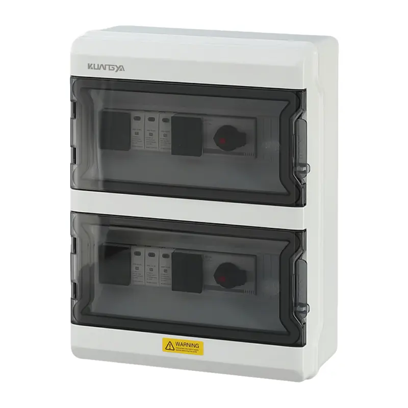
A PV combiner box is more than just a junction box. It is an essential piece of equipment that merges the output of multiple solar strings into a single output, while providing vital protection, isolation, and monitoring capabilities. Getting the selection right is paramount for the safety, reliability, and performance of any large-scale solar project.
In any system with more than two or three strings, a combiner box serves four primary functions:
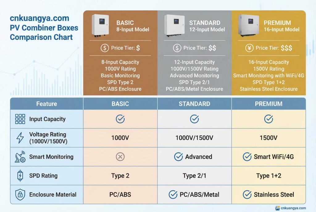
Correctly sizing a combiner box is a methodical process. Follow these six steps, referencing data from your PV module and inverter datasheets, to ensure your selection is safe and efficient.
Step 1: Determine the System Voltage Level (1000V vs. 1500V)
The first decision is the system’s maximum DC voltage.
Step 2: Calculate the Number of Strings and Total Current
Determine how many strings your array will have and how many you will connect to each combiner box. Boxes are available with inputs for 4, 8, 12, 16, or more strings. The total output current of the box will be the number of strings multiplied by the operating current of each string. This total current determines the required rating of the main disconnect switch.
Step 3: Select String Protection Fuses
Each string must be protected against reverse currents, which can occur if one string is shaded or faulty and other parallel strings feed current back into it. The industry-standard formula for sizing these fuses, as noted by experts at HUYU Electric, is:
Fuse Rating = Isc × 1.56
Where Isc is the short-circuit current of a single PV module (found on its datasheet). The 1.56 multiplier provides a safety factor to prevent nuisance tripping on cold, bright days when panels can temporarily exceed their rated output.
Step 4: Configure the Main DC Disconnect
The main disconnect allows you to isolate the box from the inverter. You have two primary choices:
As highlighted in cnkuangya Solar’s guides, the choice depends on the total output current and the calculated potential fault level of the system.
Step 5: Specify the Surge Protection Device (SPD)
A Surge Protection Device is a non-negotiable safety component. It protects your inverter and other electronics from damage caused by lightning strikes or grid surges by diverting excess voltage safely to the ground. For combiner boxes, a Type 2 SPD is typically required. Ensure its Maximum Continuous Operating Voltage (MOCV) is higher than your system’s maximum voltage.
Step 6: Evaluate the Enclosure Material and IP Rating
The enclosure protects the critical components inside from the elements for decades.
cnkuangya notes that the choice is climate-dependent. Polycarbonate is a durable, UV-resistant, and corrosion-free option suitable for most environments. Painted or stainless steel offers superior physical durability and is often used in large, ground-mounted utility projects. For coastal installations, stainless steel is necessary to resist salt corrosion.Let’s look at how these choices play out in real-world designs, using examples from ETEK‘s product lineup:

Even a perfectly specified box can fail if installed incorrectly. Based on common field errors highlighted by HUYU, here are three critical mistakes to avoid:

Mastering solar energy requires a dual focus: understanding the fundamental science that makes it possible, and diligently applying sound engineering principles to build safe, reliable systems. From the quantum leap of an electron to the robust engineering of a 1500V combiner box, every level of detail matters.
The PV combiner box is not just a component; it’s the guardian of your system’s DC side. By carefully following the selection steps and avoiding common pitfalls, you ensure the longevity, safety, and performance of your solar investment.
To get expert help specifying the right protection solution for your next solar project, contact the specialist team at cnkuangya.com.