Address
304 North Cardinal
St. Dorchester Center, MA 02124
Work Hours
Monday to Friday: 7AM - 7PM
Weekend: 10AM - 5PM
Address
304 North Cardinal
St. Dorchester Center, MA 02124
Work Hours
Monday to Friday: 7AM - 7PM
Weekend: 10AM - 5PM

A Senior EV Charging Engineer’s Perspective on Protection Device Selection

Type B RCBO vs. RCCB: fifteen years designing and commissioning EV charging infrastructure across residential, commercial, and industrial installations, I’ve witnessed countless scenarios where the choice between a Type B RCBO and a standalone RCCB transformed a routine fault diagnosis into either a five-minute fix or a frustrating three-hour investigation. This distinction isn’t merely theoretical—it directly impacts operational uptime, maintenance costs, and installer sanity.
Consider this familiar scenario: It’s 8:00 PM. A homeowner plugs in their electric vehicle, and suddenly, the entire garage goes dark. Or worse—the entire ground floor loses power. If you’ve installed an RCCB as the main protective device, you’ve just initiated what I call the “blackout hunt.” Every downstream circuit is now a suspect. Is it the EV charger? The garage freezer? That ancient power tool someone left plugged in? You’re hunting in the dark, both literally and figuratively.
Now imagine the same scenario with a Type B RCBO protecting the EV charging circuit specifically. The charger trips its dedicated RCBO. The kitchen lights stay on. The refrigerator continues humming. Within seconds, you know exactly where the fault lies. This fundamental difference in diagnostic clarity is why I consistently specify Type B RCBOs for EV charger installations whenever possible.
A Residual Current Circuit Breaker (RCCB)—also known as an RCD (Residual Current Device)—provides protection against earth leakage currents by monitoring the balance between line and neutral conductors. When it detects an imbalance exceeding its rated sensitivity (typically 30mA for residential applications), it disconnects the circuit.
The critical characteristic of an RCCB is its scope of protection. When installed as the main incoming protection device, it guards all downstream circuits collectively. While this provides comprehensive coverage against electric shock hazards, it creates a single point of failure that affects every connected load when tripped.
A Residual Current Breaker with Overcurrent protection (RCBO) integrates two functions within a single compact device:
The “Type B” designation specifies its residual current detection capabilities. Unlike standard Type AC or Type A devices, a Type B RCBO detects:
This comprehensive detection capability makes Type B RCBOs essential for EV charger installations, where power electronic converters can generate smooth DC fault currents that would blind traditional protection devices.
| Feature | Type B RCBO | Standalone RCCB |
|---|---|---|
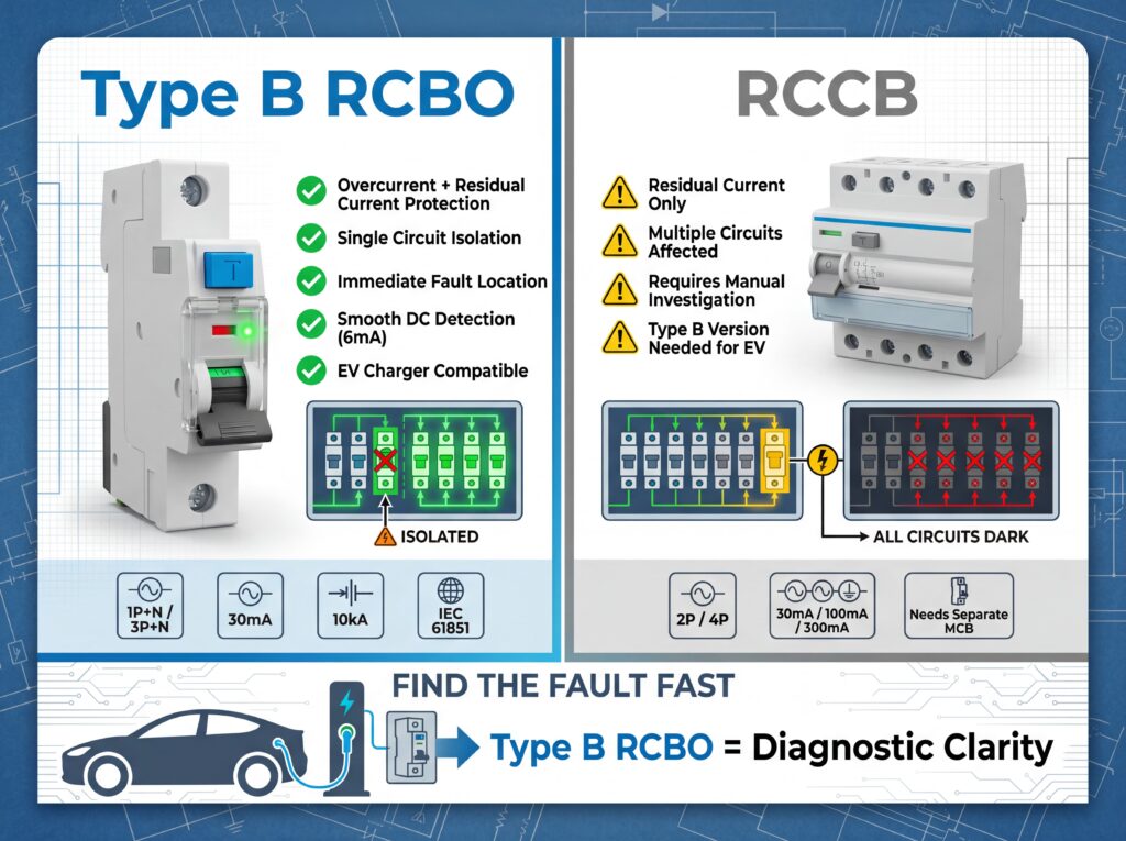
| Protection Functions | Overcurrent + Residual Current (dual protection) | Residual Current only |
| Fault Isolation Scope | Single circuit only | All downstream circuits |
| Diagnostic Clarity | Immediate fault location identification | Requires systematic investigation |
| EV Charger Compatibility | Full Type B compliance (smooth DC detection) | Type B RCCB available but no overcurrent |
| Installation Space | 2 modules (1P+N) or 4 modules (3P+N) per circuit | 2 modules (2P) or 4 modules (4P) + separate MCB |
| Trip Coordination | Precise circuit-level discrimination | Risk of unnecessary whole-system outages |
| Installation Cost | Higher per unit, lower system cost | Lower per unit, potentially higher total cost |
| Maintenance Accessibility | Individual circuit isolation | Requires main breaker for downstream isolation |
| IEC 61851 Compliance | Direct compliance for EV charging | Requires Type B specification + additional MCB |
The Situation: A 7kW home EV charger has developed an intermittent DC leakage fault due to moisture ingress in the charging cable.
With a Type B RCBO: The dedicated ev charger rcbo trips at 2:30 AM. The homeowner wakes to find only the EV charger offline. All house circuits remain energized. The fault location is immediately apparent. A visual inspection of the charging cable reveals the damage. Total diagnostic time: 10 minutes. Inconvenience level: Minimal.
With an RCCB: The main RCCB trips at 2:30 AM. The entire house loses power. The homeowner wakes in darkness, refrigerator silence, and heating system failure. They must systematically disconnect circuits to isolate the fault. Was it the EV charger? The garage door opener? The water heater? Each test cycle requires resetting the RCCB and waiting for recurrence. Total diagnostic time: 45-90 minutes. Inconvenience level: Significant.
The Situation: A commercial installation with multiple EV charging points experiences random trips during peak charging hours. The fault is thermal—expansion and contraction of connections creates intermittent high-resistance paths to earth.
With Individual Type B RCBOs: Each charging point has its own rcbo for ev charger protection. When Bay 3 trips repeatedly while Bays 1, 2, and 4 operate normally, the pattern immediately identifies Bay 3 as the problem circuit. The maintenance team can focus their thermal imaging and connection torque verification on a single known location. Total diagnostic time: 30 minutes. Customer impact: One charging bay temporarily offline.
With a Central RCCB: The main protection trips, disabling all six charging bays simultaneously. Without individual circuit monitoring, there’s no pattern to follow. Every charging point is now suspect. The maintenance team must either shut down the entire facility for testing or wait for the fault to manifest under observation. Total diagnostic time: 2-4 hours. Customer impact: Complete charging station outage, frustrated EV drivers, negative reviews.
As an engineer who’s specified thousands of distribution panels, I can tell you that installation space design often drives device selection more than technical preferences. Let’s examine the practical spatial implications.
Type B RCBO Space Requirements:
RCCB + MCB Combination Space Requirements:
For a typical residential EV charging installation with a single 7kW charger, the Type B RCBO actually occupies less DIN rail space than the separate RCCB-plus-MCB alternative. This space efficiency becomes even more pronounced in multi-charger commercial installations.
When designing distribution panels for EV charging infrastructure, I follow these spatial optimization principles:
Circuit Separation Strategy: Position ev charger rcbo devices in dedicated sections of the distribution panel, separated from general lighting and appliance circuits. This physical grouping reinforces the logical separation and simplifies maintenance access.
Service Loop Allowance: When installing rcbo for ev charger protection, ensure adequate cable service loops are provided. The diagnostic process often involves temporary removal or testing—sufficient slack prevents strain on terminals and facilitates troubleshooting.
Thermal Management: Modern Type B RCBOs with continuous EV charging loads generate heat. Ensure panel ventilation accounts for sustained 32A or 40A operation. I typically specify 20% additional ventilation capacity when multiple EV charging circuits are concentrated in a single enclosure.
The EV charging landscape evolves rapidly. Today’s 7kW residential charger may be tomorrow’s 11kW or 22kW unit. When allocating panel space, consider these expansion scenarios:
Absolutely not—and this is where cutting corners becomes genuinely dangerous. As a senior EV charging engineer, I cannot emphasize strongly enough that Type B protection is mandatory for EV charging applications, not optional.
Here’s the technical reality: EV chargers use power electronic converters that transform AC supply to DC for battery charging. When insulation failures occur, these converters can produce smooth DC residual currents—continuous unidirectional current without the alternating component that Type A devices detect. This smooth DC current causes “DC blinding” in Type A devices, saturating their magnetic cores and rendering them unable to detect subsequent AC fault currents.
IEC 61851-1:2017 and BS 7671:2018+A2:2022 explicitly mandate Type B protection where smooth DC residual current protection is required. Using a Type A device creates a false sense of security—the device appears functional, but it’s blind to the specific fault conditions most likely to occur in EV charging scenarios.
The Type B RCBO incorporates specialized magnetic circuits that detect smooth DC residual currents up to 6mA while maintaining full sensitivity to AC faults at 30mA. This dual capability ensures comprehensive protection throughout all phases of the charging cycle. The cost difference between Type A and Type B is insignificant compared to the safety assurance provided.
Technically possible? Yes. Professionally advisable? Absolutely not.
When you install a single RCCB protecting multiple EV charging circuits, you create the exact diagnostic nightmare this article describes. Consider the operational reality: you have three EV chargers sharing a single 30mA RCCB. Charger A develops a cable fault, Charger B operates normally, and Charger C completes its cycle without issue. The RCCB trips, disconnecting all three chargers simultaneously.
Now you’re faced with systematic isolation testing—disconnecting each charger individually, resetting the RCCB, and waiting for the fault to recur. During this diagnostic process, all charging operations are suspended. If this is a commercial installation, you’re losing revenue with every minute of investigation. If it’s residential, you’re explaining to multiple EV owners why their vehicles aren’t charging.
The proper engineering solution is individual Type B RCBO protection for each EV charging circuit. Yes, this requires more DIN rail space and higher initial investment. But the diagnostic clarity, operational continuity, and maintenance simplicity deliver return on investment through reduced downtime and faster fault resolution.
For panel space constraints, consider upgrading to a larger distribution enclosure or implementing a sub-distribution panel specifically for EV charging circuits. The incremental cost of proper circuit separation pales in comparison to the operational costs of undifferentiated fault investigation.
Selecting the appropriate ev charger rcbo rating requires consideration of continuous operation, inrush characteristics, and future expansion. Let me walk you through the calculation methodology I use in my designs.
Step 1: Determine Maximum Continuous Current
For a typical 7kW single-phase EV charger:\
$I_{rated} = \frac{P}{V \times \eta} = \frac{7000W}{230V \times 0.95} \approx 32A$
Step 2: Apply Continuous Operation Factor
EV charging represents continuous loading (potentially 6-8 hours). IEC standards recommend derating by 20% for continuous loads:\
$I_{protection} \geq I_{rated} \times 1.25 = 32A \times 1.25 = 40A$
Therefore, for a 7kW charger, I specify a 40A Type B RCBO rather than the minimum 32A rating. This provides thermal headroom for sustained operation during long charging cycles.
Step 3: Select Tripping Curve
Step 4: Residual Current Sensitivity
Standard 30mA Type B RCBOs are appropriate for residential EV charging. For commercial installations with multiple chargers, you may consider 100mA sensitivity with supplementary 30mA protection at individual charging points (subject to local regulations).
Step 5: Verify Breaking Capacity
Ensure the rcbo for ev charger has adequate breaking capacity for your installation’s prospective fault current. Most residential applications require minimum 6kA, but I typically specify 10kA for additional safety margin.
Based on my field experience with various manufacturers, the KUANGYA VRL11 Type B RCBO offers an excellent balance of performance, certification, and value for EV charging applications:
| Specification | KUANGYA VRL11 Value |
|---|---|
| Configuration | 1P+N (Single-pole + Neutral) |
| Rated Current (In) | 5–40A |
| Rated Voltage (Ue) | AC 240V / AC 120V |
| Residual Current Type | Type B (AC, pulsating DC, smooth DC to 6mA) |
| Rated Residual Current (IΔn) | 30mA |
| Breaking Capacity (Icn) | 10kA @ 240V / 15kA @ 120V |
| MCB Tripping Curve | B (3–5×In) or C (5–10×In) |
| Standards Compliance | IEC/EN 61009-1, IEC 62943 |
| Certifications | SEMKO, UKCA, CE, SAA |
The choice between a Type B RCBO and an RCCB for EV charging protection transcends simple regulatory compliance. It represents an engineering decision that directly impacts operational efficiency, maintenance burden, and diagnostic clarity for the entire service life of the installation.
From my fifteen years of experience in the field, installations featuring individual ev charger rcbo protection consistently demonstrate superior uptime, faster fault resolution, and lower total cost of ownership compared to shared RCCB configurations. The incremental investment in proper circuit-level protection yields returns through reduced investigation time, minimized unnecessary outages, and enhanced system reliability.
When designing your next EV charging installation, remember the fundamental principle: Protection should clarify faults, not obscure them. The Type B RCBO embodies this principle by providing precise, circuit-level protection that tells you exactly where problems exist—saving time, money, and frustration when every minute of diagnostic delay matters.
Find the fault fast. Specify Type B RCBOs for your EV charging installations.
Note: This article reflects the professional opinions and field experience of a senior EV charging infrastructure engineer. Always consult local electrical codes and manufacturer specifications for your specific installation requirements. Standards and regulations may vary by jurisdiction.
