WengYang Industrial Zone Yueqing Wenzhou 325000
Work Hours
Monday to Friday: 7AM - 7PM
Weekend: 10AM - 5PM
WengYang Industrial Zone Yueqing Wenzhou 325000
Work Hours
Monday to Friday: 7AM - 7PM
Weekend: 10AM - 5PM
It’s 2:47 AM when the security system alerts the facility manager to unusual thermal signatures in Solar Combiner Box #3. Racing to the rooftop installation, he discovers what every solar professional dreads: a sustained DC arc, glowing at over 3,000°C (5,400°F), slowly consuming the copper terminals inside. The arc has been burning for hours—silently, invisibly—fed by the relentless energy of a 1000V photovoltaic array. Minutes more, and the dry roofing membrane below would have ignited.
The investigation reveals a critical mistake: the wrong overcurrent protection device. While the component was labeled as a “circuit breaker,” it lacked the specialized arc-quenching mechanisms required for high-voltage DC applications. Unlike AC systems where current naturally crosses zero 120 times per second, DC maintains constant voltage—giving arcs unlimited energy to sustain themselves and turn minor faults into catastrophic failures.
As a Senior Application Engineer with over 15 years designing solar protection systems, I’ve witnessed this scenario play out too many times. The choice between DC fuses and DC circuit breakers isn’t just about upfront cost or convenience—it’s a decision that impacts system safety, operational reliability, and total lifecycle economics over your installation’s 25-year lifespan. This isn’t a surface-level comparison of pros and cons. This is an engineering-level analysis that will help you select the right overcurrent protection device (OCPD) for your specific PV application, backed by technical data, code requirements, and real-world performance metrics.
Before comparing solutions, we must understand the unique threat that makes DC protection so critical. The fundamental physics of Direct Current creates a fire hazard that simply doesn’t exist in standard AC electrical systems.
In an AC system operating at 60 Hz, voltage and current wave back and forth, crossing through zero volts 120 times every second. Each zero-crossing event is a natural opportunity for an electrical arc to extinguish itself. Think of it like a candle flame in a rhythmic breeze—the flame repeatedly diminishes and must re-establish itself 120 times per second. Eventually, if conditions aren’t perfect, the flame goes out.
DC is fundamentally different. It’s a constant, unrelenting flow of energy in one direction—like a steady river that never ebbs. Once an arc forms between conductors (from a loose connection, damaged insulation, or moisture ingress), there is no zero-crossing to help extinguish it. The arc becomes a self-sustaining plasma bridge—a “blowtorch” that can maintain temperatures exceeding 3,000°C, easily melting copper, aluminum, and steel while igniting any nearby combustible materials.
Modern solar arrays operate at increasingly high DC voltages: 600V for residential systems, 1000V for commercial installations, and up to 1500V for utility-scale projects. Higher voltage makes arcs easier to initiate and provides more energy to sustain them. A 1000V DC arc has exponentially more destructive power than a 120V AC arc—it can jump larger air gaps, penetrate deeper into enclosures, and maintain itself across carbonized insulation that would normally be non-conductive.
This is why you can never use a standard AC-rated breaker or fuse in a DC application. AC protection devices lack the internal arc-quenching mechanisms required to safely interrupt DC circuits under load. Installing an AC device on a DC system is a code violation that creates immediate fire and explosion hazards.
graph LR
    A[AC Current] -->|Zero-Crossing 120x/sec| B[Natural Arc Extinction]
    C[DC Current] -->|Constant Voltage| D[Self-Sustaining Arc]
    D -->|3000°C Plasma| E[Equipment Damage]
    D -->|Ignition Source| F[Fire Hazard]

    style D fill:#ff6b6b
    style E fill:#ff6b6b
    style F fill:#ff6b6b
    style B fill:#51cf66
Key Takeaway #1: DC arcs are self-sustaining plasma bridges that won’t extinguish naturally like AC arcs. They can burn indefinitely at temperatures exceeding 3,000°C, creating severe fire risks. This is why specialized DC-rated overcurrent protection devices with proper voltage ratings and arc-interrupting mechanisms are absolutely non-negotiable for solar PV systems. Using AC-rated devices on DC circuits violates NEC 110.3(B) and creates life-safety hazards.
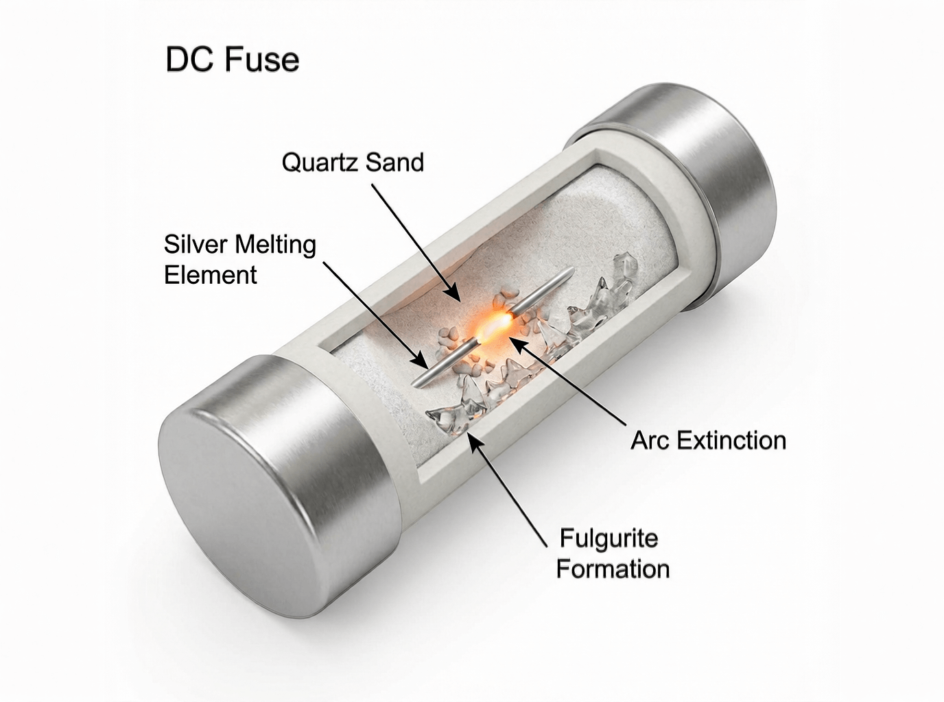
The DC fuse represents the oldest and most fundamental approach to overcurrent protection—a precisely engineered component designed to destroy itself to save your system. For solar applications, we don’t use generic fuses; we use gPV-rated fuses (per UL 2579 and IEC 60269-6) specifically formulated for photovoltaic system protection.
At the heart of every fuse is a metallic element—typically silver, copper, or a specialized alloy—precisely calibrated to melt at a specific current level. The element’s cross-sectional area, length, and material composition determine its time-current characteristics.
When current exceeds the fuse’s rating, resistive heating occurs. For minor overloads (125-150% of rating), the element heats gradually over seconds or minutes until it melts. For severe short circuits (500-1000% of rating), the element vaporizes almost instantaneously—in as little as 0.004 seconds—entering what’s called the “current-limiting” range.
But melting the element is only half the story. When the element vaporizes, it creates a dangerous DC arc across the gap. This is where specialized DC fuse construction becomes critical:
1. Voltage Rating (VDC): Must equal or exceed your system’s maximum open-circuit voltage (Voc) adjusted for the coldest expected temperature. For a string producing 460V at standard test conditions, cold-weather Voc might reach 525V, requiring a 600V-rated fuse.
2. Current Rating (Amperes): NEC 690.8 requires sizing at 156% of the circuit’s short-circuit current (Isc). For a module rated 9.8A Isc: 9.8A × 1.56 = 15.3A minimum, so you’d select a 20A fuse (next standard size up).
3. Interrupting Capacity (AIC): This is the maximum fault current the fuse can safely clear without exploding. Solar fuses commonly offer 20kA, 50kA, or even 100kA ratings—far exceeding what most circuit breakers can achieve at comparable cost.
Ultra-High Interrupting Capacity: A 20A gPV fuse rated at 50,000 AIC costs $15-25. A DC circuit breaker with equivalent AIC would cost $200-400. For high-fault-current applications (near battery banks or in large combiner boxes), fuses provide superior protection more economically.
Fastest Response Time: Current-limiting fuses operate in 4 milliseconds or less during short circuits, drastically limiting let-through energy (I²t). This protects expensive downstream equipment like inverters and charge controllers from thermal and mechanical stress.
Inherent Simplicity: With no moving parts, fuses cannot fail mechanically. They fail in a predictable “open” (safe) state. There’s no calibration drift, no lubrication to dry out, no contacts to weld together.
Lower Initial Cost: The fuse plus holder typically costs 20-40% less than an equivalent DC circuit breaker, making them attractive for large projects with hundreds of strings.
Single-Use Operation: Once blown, the fuse must be replaced entirely. This requires maintaining spare inventory and involves system downtime while a technician accesses the combiner box and installs a new fuse.
Human Error Risk: There’s nothing preventing someone from replacing a 15A fuse with a 30A fuse—a dangerous scenario that undermines all protection. Training and clear labeling are essential.
No Switching Function: A fuse provides protection but cannot serve as a manual disconnect switch. For maintenance isolation, you need a separate disconnect device, adding cost and enclosure space.
Troubleshooting Challenges: In a combiner box with twelve fuses, a single blown fuse requires visual inspection or continuity testing to identify which string has failed.
Key Takeaway #2: DC fuses offer the most robust, fast-acting overcurrent protection available, with interrupting capacities up to 100kA at remarkably low cost. Their sacrificial, single-use nature makes them ideal for applications prioritizing maximum safety and fault current handling. However, each fault event requires manual replacement, which introduces operational downtime and potential for incorrect replacement—making them best suited for systems with low fault frequency and professional maintenance access.
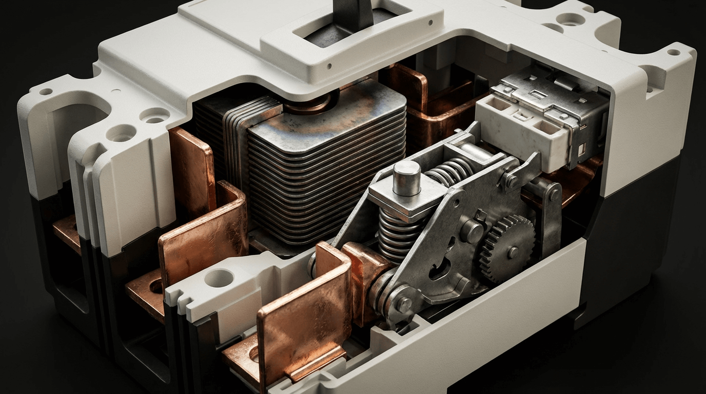
If a DC fuse is a sacrificial soldier on a one-way mission, a DC circuit breaker is a highly trained guard who can stop a threat and immediately return to duty. A breaker combines overcurrent protection with manual switching capability—and critically, it can be reset after tripping without requiring component replacement.
DC circuit breakers designed for solar applications (rated per UL 489 for larger units or UL 1077 for supplementary protectors) use a sophisticated dual-mechanism approach:
Thermal Trip for Overloads: A bimetallic strip—made from two metals with different thermal expansion rates bonded together—sits in series with the circuit. Under sustained overcurrent (125-200% of rating), the strip heats up, bending proportionally to the current level. When it bends enough, it releases a spring-loaded latch, and the contacts snap open. This handles the “slow burn” overloads—like a string carrying 18A continuous when rated for 15A.
Magnetic Trip for Short Circuits: A solenoid coil surrounding the current path generates a magnetic field proportional to current flow. During a severe short circuit (typically 5-20× rated current), the magnetic field becomes strong enough to instantly pull a plunger that mechanically trips the breaker. This provides near-instantaneous protection (0.02-0.05 seconds) for dangerous fault conditions.
This dual-mechanism design creates the distinctive “two-zone” time-current curve that defines circuit breaker behavior—a gradual thermal response to overloads and an instantaneous magnetic response to short circuits.
The real engineering challenge in a DC breaker is extinguishing the arc that forms when the contacts separate under load. This is accomplished through the arc chute—a sophisticated chamber containing a series of parallel metal plates.
When the breaker trips, the contacts separate, creating an arc. Magnetic “blowout” coils immediately push this arc upward into the arc chute. The metal plates divide the single large arc into multiple smaller, cooler arcs in series. These series arcs have higher total voltage drop, which opposes the system voltage, making it harder for current to flow. Simultaneously, the plates absorb heat, cooling the arcs until they can no longer sustain themselves and extinguish.
This is why DC breakers are larger and more expensive than equivalent AC breakers—the arc chute must be significantly more robust to handle DC’s sustained arc energy.
Resettable Operation: After clearing a fault, simply reset the handle to restore power. For nuisance trips or temporary overloads, this saves hours of downtime compared to fuse replacement. In remote installations, this can prevent expensive service calls.
Dual-Function Design: The breaker serves as both protection and a manual disconnect switch. This satisfies NEC 690.13 requirements for a photovoltaic disconnect means, eliminating the need for a separate disconnect device.
Predictable Performance: The trip characteristics remain stable over the breaker’s life (typically 20-30 years). Unlike fuses which might be incorrectly replaced, the breaker’s rating cannot be changed—it’s permanently determined by the internal mechanism.
Multi-Pole Coordination: Breakers can be mechanically or electrically ganged so that a fault on any pole trips all poles simultaneously. This is critical for multi-string combiner boxes where you want complete circuit isolation.
Diagnostic Capability: A tripped breaker provides immediate visual indication of a problem. Some advanced models include remote monitoring contacts for SCADA integration.
Higher Initial Investment: A quality DC circuit breaker costs 3-10× more than an equivalent fuse and holder. For a 400A combiner-level breaker, expect to pay $500-1,500 compared to $100-200 for a fuse-based solution.
Lower Interrupting Capacity: Standard molded case circuit breakers (MCCBs) typically offer 10-25kA interrupting capacity. Achieving 50kA+ ratings requires expensive specialized models, whereas fuses routinely provide these ratings as standard.
Mechanical Wear: Breakers contain springs, latches, and moving contacts subject to mechanical fatigue. While rare, mechanisms can bind, contacts can weld during high-current events, and calibration can drift over decades. Manufacturers recommend periodic “exercising” (manually cycling on/off) to maintain mechanical freedom.
Slower Response Time: While the magnetic trip is fast (20-50ms), it’s still 5-12× slower than a current-limiting fuse’s 4ms response. This allows more let-through energy (I²t), potentially stressing downstream components.
Key Takeaway #3: DC circuit breakers provide exceptional operational flexibility through their resettable nature and integrated disconnect functionality. Their thermal-magnetic trip mechanism and specialized arc chutes enable safe DC interruption, but this sophistication comes at significantly higher cost. Breakers excel in applications requiring frequent maintenance access, remote operation capability, or where system uptime is the primary concern—provided the application’s fault current doesn’t exceed the breaker’s interrupting capacity.
To make an informed engineering decision, we need to compare these technologies across the parameters that actually matter in real-world solar installations: safety performance, economic impact, and operational characteristics.
| Feature | DC Fuse (gPV) | DC Circuit Breaker | Engineering Analysis |
|---|---|---|---|
| Arc Interruption Method | Melting element creates gap; silica sand absorbs arc energy | Arc chute divides arc into multiple series arcs, cooled by metal plates | Both effective; fuse interruption is passive/chemical, breaker is active/mechanical |
| Interrupting Capacity (AIC) | 20kA-100kA standard, up to 200kA available | 10kA-25kA standard, 50kA-100kA for premium models | Fuses provide higher AIC more economically—critical near battery banks where fault current can exceed 50kA |
| Response Time (High Fault) | 0.004-0.010 seconds (4-10ms) in current-limiting range | 0.020-0.050 seconds (20-50ms) for magnetic trip | Fuses are 5-12× faster, limiting let-through energy (I²t) to protect sensitive inverters and charge controllers |
| Let-Through Energy (I²t) | Extremely low due to current-limiting action | Moderate—allows more energy during interruption | Lower I²t means less thermal and mechanical stress on all downstream components |
| Failure Mode | Always fails “open” (safe condition) | Can fail “closed” if contacts weld during extreme fault | Fuses inherently fail-safe; breakers require proper sizing to prevent contact welding |
| Nuisance Tripping | Rare with proper gPV sizing and temperature correction | Thermal trip can be sensitive to ambient temperature in hot combiner boxes | Both require proper sizing; breakers offer slight advantage with adjustable thermal trip on some models |
This analysis assumes a typical commercial installation with eight strings feeding a combiner box, experiencing three fault events over 20 years, with moderate maintenance labor costs.
| Cost Category | Fuse-Based System (8 strings) | Breaker-Based System (8 strings) | Delta |
|---|---|---|---|
| Initial Equipment | 8× 20A fuse holders: $240 8× gPV fuses: $160 Main 100A fuse: $80 Total: $480 | 8× 20A DC breakers: $1,200 Main 100A DC breaker: $600 Total: $1,800 | Breakers cost $1,320 more upfront |
| Installation Labor | Simpler wiring, less torque requirements 6 hours @ $85/hr = $510 | More complex terminal connections 8 hours @ $85/hr = $680 | Breakers add $170 installation cost |
| Spare Parts Inventory | 16× replacement fuses (2× each rating) $320 initial, $0 annually | No consumables required $0 | Fuses require $320 spares |
| Fault Event Service (3× over 20 years) | Each event: 1 hour diagnosis + 1 hour replacement + 45 min travel $233 per event × 3 = $699 | Each event: 30 min diagnosis + 15 min reset + 45 min travel $127 per event × 3 = $381 | Breakers save $318 on service calls |
| Downtime Cost (3 events) | Average 4 hours per event @ $150/hr production loss $600 per event × 3 = $1,800 | Average 1.5 hours per event @ $150/hr $225 per event × 3 = $675 | Breakers save $1,125 on downtime |
| Testing/Maintenance (20 years) | Annual visual inspection: $50/yr 20 years = $1,000 | Annual exercising + inspection: $100/yr 20 years = $2,000 | Breakers add $1,000 maintenance cost |
| End-of-Life Replacement | Same as initial equipment $480 | Same as initial equipment $1,800 | Breakers cost $1,320 more |
| 20-YEAR TOTAL | $5,289 | $7,336 | Fuses save $2,047 (28% lower TCO) |
Critical Insight: The TCO analysis shifts dramatically based on fault frequency and downtime costs. For systems with frequent nuisance trips or downtime costs exceeding $500/hour, breakers become economically favorable despite higher equipment costs.
| Specification | DC Fuse (gPV) | DC Circuit Breaker | Selection Guidance |
|---|---|---|---|
| Voltage Ratings | 600VDC, 1000VDC, 1500VDC | 600VDC, 1000VDC, 1500VDC | Equal availability; verify rating matches or exceeds cold-weather Voc × 1.15 |
| Current Ratings (String Level) | 1A-30A in standard increments | 10A-63A (limited low-current options) | Fuses offer more granular sizing for small strings; breakers start at 10A minimum |
| Operating Temperature | -40°C to +85°C (standard) | -25°C to +70°C (derating required above 40°C) | Fuses better suited for extreme hot/cold environments; breaker thermal trip is temperature-sensitive |
| Certification Standards | UL 2579 (gPV fuse), IEC 60269-6 | UL 489 (MCCB), UL 1077 (supplementary), IEC 60947-2 | Verify both voltage AND current ratings are DC-certified; AC ratings are meaningless |
| Physical Size (20A rating) | 10mm × 38mm cylindrical + holder | 18mm wide DIN rail mount | Fuses 60% more compact—important in crowded combiner boxes |
| Installation Complexity | Spring-clip holder (no torque spec) | Terminal screws (specific torque required) | Fuses faster to install but offer less robust connection; breakers require torque wrench |
| Field Serviceability | Requires fuse puller tool, replacement inventory | Reset with handle; no tools or spares | Breakers eliminate need for on-site spare parts inventory |
The amp rating tells you if a device will protect; the time-current curve tells you when. Understanding these curves is essential for proper coordination and selective protection in solar systems.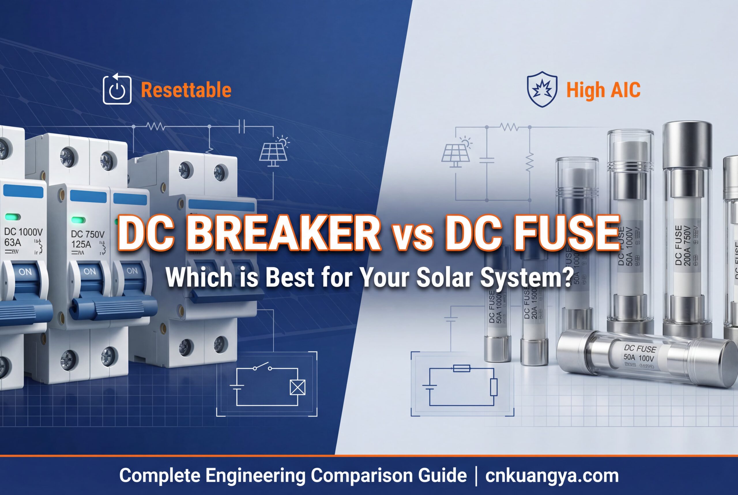
A time-current curve (TCC) plots fault current (x-axis) against the time required for the protection device to open (y-axis, logarithmic scale). The curve shows that devices respond faster to higher currents—following an “inverse time” relationship.
DC Fuse Characteristic: A simple, smooth inverse-time curve. At low overloads (150% of rating), the fuse may take 600+ seconds to melt. At high fault currents (1000% of rating), it melts in 4-10 milliseconds, entering its “current-limiting” range where it actually prevents fault current from reaching its theoretical maximum.
DC Breaker Characteristic: A two-zone curve:
%%{init: {'theme':'base', 'themeVariables': { 'primaryColor':'#f0f0f0'}}}%%
xychart-beta
    title "Time-Current Curves: Fuse vs Breaker Response"
    x-axis "Current (Multiple of Rated Current)" [1, 2, 5, 10, 20, 50, 100]
    y-axis "Time to Trip (Seconds)" [0.01, 0.1, 1, 10, 100, 1000]
    line "20A gPV Fuse" [800, 60, 3, 0.15, 0.03, 0.006, 0.004]
    line "20A DC Breaker" [900, 180, 25, 8, 0.04, 0.04, 0.04]
The total energy delivered during a fault is proportional to I²t (current squared × time). A fuse clearing in 4ms at 1000A delivers far less destructive energy than a breaker clearing in 40ms at the same current:
The breaker allows 10× more energy through before clearing. This additional energy creates mechanical forces (proportional to I²), thermal stress, and potential damage to inverter input capacitors, DC contactors, and wiring insulation.
Engineering Application: In systems with expensive inverters or sensitive electronics, the lower let-through energy of current-limiting fuses provides superior component protection, potentially extending equipment life by preventing cumulative fault stress.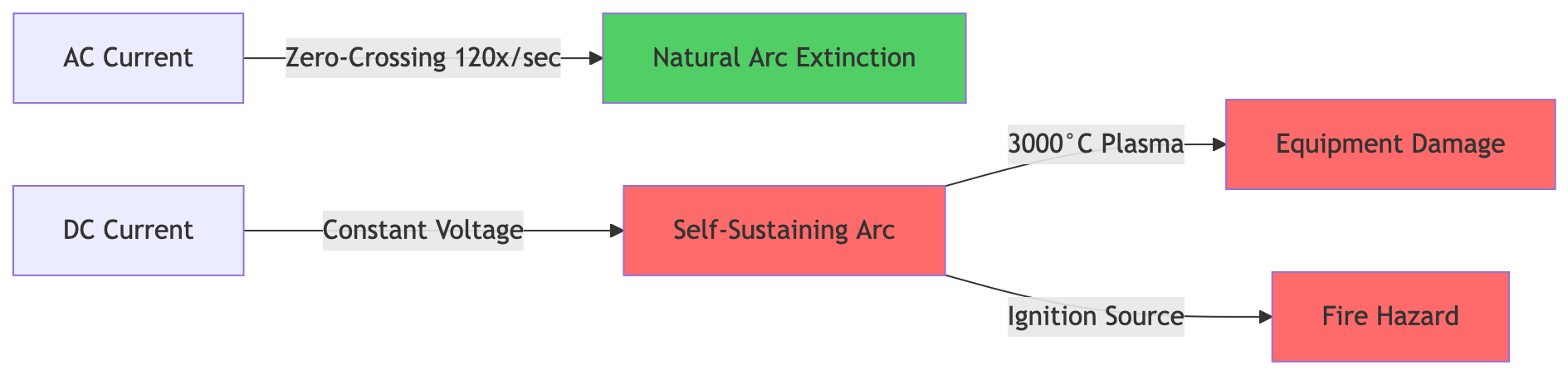
Key Takeaway #4: Time-current curves reveal the fundamental difference in protection philosophy: fuses provide a single, fast-acting inverse-time response that dramatically limits fault energy, while breakers offer a tunable two-zone response that tolerates temporary overloads but responds slower to short circuits. For applications prioritizing maximum equipment protection, fuses’ superior I²t characteristics deliver measurable advantages. For systems requiring tolerance of inrush currents or temporary overloads, breakers’ adjustable thermal trip provides operational flexibility.
Theory and specifications are essential, but solar projects require actionable decisions. Use this framework to select the right protection architecture for your specific installation.
Maximum System Voltage: Determine the open-circuit voltage (Voc) of your longest string at the coldest expected temperature:
Maximum Circuit Current: Calculate the continuous current capacity requirement:
Available Fault Current: This determines required interrupting capacity (AIC). For string combiners fed by 8-12 strings:
For battery systems, fault current calculation is more complex—batteries can deliver 10,000-50,000A depending on bank size and cable length. This often drives selection toward high-capacity fuses (20kA-100kA AIC) due to cost considerations.
NEC Article 690 Mandatory Requirements:
Installation Location Considerations:
| Location | Fuse Advantages | Breaker Advantages | Recommendation |
|---|---|---|---|
| String combiner (rooftop) | High AIC, compact size, low cost | Visual trip indication, no replacement inventory | Fuses for cost-sensitive installations Breakers for easy troubleshooting |
| Ground-level recombiner | Simple, proven technology | Acts as required disconnect, resettable | Breakers for operational convenience |
| Battery circuit | Extremely high AIC (50kA-100kA) economically available | Resettable for battery maintenance procedures | Fuses for ultimate safety Breakers if AIC requirement < 25kA |
| Inverter input | Fast let-through energy limitation | Serves as required disconnect per NEC 690.13 | Breakers to satisfy code and protect inverter |
Site Accessibility:
Downtime Tolerance:
Maintenance Capabilities:
Troubleshooting Needs:
Use the framework from Section 4’s economic analysis, adjusted for your specific parameters:
When Fuses Win Economically:
When Breakers Win Economically:
Break-Even Analysis Example: For an 8-string system with projected two fault events over 20 years and downtime costs of $200/hour, fuses deliver ~$1,500 lower TCO. If downtime costs exceed $600/hour, breakers become economically favorable.
Choose DC Fuses When:
Choose DC Circuit Breakers When:
Consider Hybrid Approach:
Most optimally designed systems use both technologies strategically:
This hybrid architecture provides code compliance, operational convenience, and cost optimization simultaneously.
Typical Configuration: 8-16 strings of 300-400W panels feeding a string inverter
Recommended Protection:
Special Considerations: NEC 690.11 requires arc-fault protection for roof-mounted systems. This is typically integrated in the inverter, but verify compatibility with your fuse/breaker configuration.
Typical Configuration: Multiple combiner boxes (8-12 strings each) feeding central recombiner and inverter
Recommended Protection:
Special Considerations: Arc-flash hazard analysis per NFPA 70E is required for worker safety. Current-limiting fuses can significantly reduce arc-flash incident energy and PPE requirements.
Critical Requirement: Battery banks can deliver 10,000A+ into short circuits. This demands exceptional interrupting capacity.
Recommended Protection:
Critical Safety Note: Battery circuit protection is life-critical. Always perform short-circuit current calculation accounting for battery internal resistance and cable impedance. Undersized AIC ratings can cause explosive device failure.
Configuration: Centralized DC switchgear with SCADA control and remote operation
Recommended Protection:
Special Considerations: Utility-scale projects require professional engineering studies for protection coordination, arc-flash analysis, and O&M optimization. The fuse-vs-breaker decision should follow comprehensive system analysis, not generic rules.
Q: Can I use an AC circuit breaker for my DC solar system?
A: Absolutely not—this is dangerous and a code violation. AC breakers lack the arc-quenching mechanisms required to safely interrupt DC current. DC arcs don’t have zero-crossings like AC, making them exponentially harder to extinguish. An AC breaker may fail to open during a DC fault, causing contacts to weld together and creating a permanent short circuit—leading to fire or explosion. Always verify your breaker has a DC voltage rating (e.g., “600VDC”) equal to or greater than your system voltage.
Q: What does the kA or AIC rating really mean, and why does it matter?
A: AIC stands for Ampere Interrupting Capacity (sometimes called Interrupt Rating or IR). It’s the maximum fault current the device can safely clear without exploding or sustaining damage. If fault current exceeds the AIC rating, the device may rupture violently, spraying molten metal and causing catastrophic failure.
For solar string combiners, typical fault currents range from 100-500A, so any 10kA+ device is adequate. But near battery banks, where fault current can reach 20,000-50,000A, you need fuses or breakers specifically rated for these extreme levels. This is why Class T fuses (100kA-200kA AIC) are standard for battery disconnects—they provide the necessary capacity economically.
Q: Which is safer—a fuse or a circuit breaker?
A: Both provide excellent protection when properly applied. The safety difference is nuanced:
Fuses offer:
Breakers offer:
For ultimate protection of expensive equipment, fuses’ lower let-through energy provides measurable advantage. For worker safety during maintenance, breakers’ integrated disconnect function is valuable. Most systems use both strategically.
Q: How do I size protection devices per NEC 690.8 requirements?
A: NEC 690.8(A)(1) requires solar circuit overcurrent devices to be rated at minimum 156% of the circuit’s short-circuit current (Isc):
Example Calculation:
This 56% oversizing factor accounts for variations in solar irradiance (125% for high-sun conditions) plus an additional 125% continuous current safety margin = 1.25 × 1.25 = 1.56.
For voltage rating, use maximum cold-weather Voc multiplied by 1.14-1.25 (depending on climate), then select next standard voltage rating up.
Q: What’s the difference between UL 2579 (fuses) and UL 489 (breakers)?
A: These are the primary safety standards for solar overcurrent protection:
Always verify both the UL listing AND the DC voltage/current ratings on the device label. A breaker listed to UL 489 but rated only for AC cannot be used on DC circuits.
Q: Why are DC circuit breakers so much more expensive than fuses?
A: DC breakers cost 5-20× more than equivalent fuses due to:
The price premium reflects genuine engineering complexity—DC arc interruption is significantly more challenging than AC.
Q: Can fuses and breakers be used together in the same system?
A: Absolutely—this is actually the recommended approach for many installations. A hybrid architecture leverages each technology’s strengths:
Common Hybrid Configuration:
The key requirement is proper selective coordination—ensuring the device closest to the fault opens first. This requires analyzing the time-current curves to verify that during any fault, the upstream device doesn’t trip before the downstream device clears.
Q: What is selective coordination and why does it matter?
A: Selective coordination means that during a fault, only the overcurrent device immediately upstream of the fault opens—leaving the rest of the system operational. This prevents a single-string fault from shutting down an entire array.
NEC 700.28 and 701.27 require selective coordination for emergency and legally required standby systems. For solar systems, proper coordination:
Achieving Coordination:
Current-limiting fuses inherently provide better coordination than breakers due to their single, predictable time-current curve.
After 15+ years designing protection systems for solar installations ranging from 5kW residential to 100MW+ utility-scale, I’ve learned that the “best” overcurrent protection device is the one that aligns with your specific operational priorities, budget constraints, and risk tolerance.
Choose DC fuses when your priority is:
Choose DC circuit breakers when your priority is:
Implement a hybrid strategy when:
The solar industry is evolving beyond the false dichotomy of “fuse vs. breaker.” The most sophisticated modern installations use both technologies strategically—placing each device where its specific strengths provide maximum value. Your protection architecture should follow your system’s unique requirements, not generic industry assumptions.
Whatever you choose, ensure every device carries proper DC voltage and current ratings, appropriate AIC for available fault current, and relevant UL certifications. The few hundred dollars saved by compromising on protection quality isn’t worth the catastrophic risk of DC arc flash events or code violations that can invalidate your entire installation.
Need expert guidance on protection system design? Contact cnkuangya.COM‘s certified solar engineers for a comprehensive site-specific analysis that optimizes safety, reliability, and lifecycle costs for your specific installation parameters.
