WengYang Industrial Zone Yueqing Wenzhou 325000
Work Hours
Monday to Friday: 7AM - 7PM
Weekend: 10AM - 5PM
WengYang Industrial Zone Yueqing Wenzhou 325000
Work Hours
Monday to Friday: 7AM - 7PM
Weekend: 10AM - 5PM
I once got a frantic call from a project manager at a newly commissioned 5-megawatt solar farm. Their brand-new, multi-million-dollar system was experiencing random, cascading shutdowns. The culprit wasn’t a faulty inverter or a damaged panel; it was a $10 fuse, incorrectly specified, causing nuisance trips that brought a significant portion of the plant offline for weeks. That tiny component cost the client tens of thousands in lost revenue and emergency service calls.
As a senior application engineer who has spent decades in the trenches of overcurrent protection design, I’ve seen firsthand how a seemingly minor oversight in fuse selection can lead to catastrophic failures. In the world of high-voltage Direct Current (DC) systems, particularly in solar and renewable energy projects, fuses are not just simple commodities; they are the silent guardians of your system’s safety, reliability, and financial viability.
Specifying them correctly is a non-negotiable engineering discipline. Unfortunately, I see the same critical mistakes being made time and again. This article isn’t about theory; it’s about sharing hard-won lessons from the field. Here are the top 10 mistakes I see engineers and installers make when specifying DC fuses—and how you, the professional, can get it right.
The Mistake: This is the cardinal sin of DC protection. An installer, perhaps out of convenience or misunderstanding, grabs a standard AC-rated fuse (like those used in building distribution panels) and installs it in a DC combiner box.
Why It’s a Critical Problem: It’s about the arc. When a fuse blows, it creates an internal electrical arc that must be extinguished to interrupt the current. AC current naturally crosses zero volts 100 or 120 times per second, which helps the fuse extinguish the arc. DC current, however, is a relentless, continuous flow. It has no zero-crossing. A DC arc, once established, will sustain itself like a plasma blowtorch, drawing continuous power from the source. An AC fuse in a DC circuit lacks the specific internal design (longer arc paths, specialized filler) to quench this sustained DC arc. The result? The fuse holder can melt, the enclosure can catch fire, and a simple fault can escalate into a catastrophic failure.
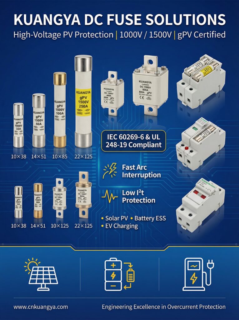
The Professional’s Solution: Never use an AC-rated fuse in a DC circuit. Always use fuses specifically marked and rated for DC applications. The fuse body will clearly state its VDC (Volts DC) rating. For solar, you must go a step further and use “gPV” rated fuses, which are specifically designed for the unique demands of photovoltaic systems.
| Feature | AC Fuse | DC Fuse (gPV) |
|---|---|---|
| Arc Extinguishing | Relies on AC zero-crossing | Internal arc quenching (sand, longer body) |
| Voltage Rating | Stated in VAC (e.g., 600VAC) | Stated in VDC (e.g., 1000VDC) |
| Sustained Arc Risk | Low | High (if not properly designed) |
| Typical Application | Building panels, motor controls | Solar combiner boxes, battery systems |
Key Takeaway: A fuse’s DC voltage rating is not a suggestion; it is a fundamental requirement for safely extinguishing a DC arc and preventing fire.
The Mistake: An engineer or installer selects a fuse based only on its continuous current and voltage rating, completely ignoring the Interrupting Rating, also known as Ampere Interrupting Capacity (AIC) or Breaking Capacity.
Why It’s a Critical Problem: The AIC rating is the maximum fault current a fuse can safely interrupt without rupturing or exploding. Think of it like this: stopping a bicycle moving at 10 mph is easy (a low fault current). Stopping a freight train moving at the same speed (a high fault current) requires immensely more force. If the available fault current at a location is 15,000 amps (15kA) and you install a fuse with a 5kA AIC rating, you’ve asked a bicycle brake to stop a freight train. During a major short circuit, the fuse will fail catastrophically, potentially exploding and causing an arc flash that can destroy equipment and endanger personnel.
The Professional’s Solution: Always calculate the available short-circuit current at the point of installation and select a fuse with an AIC rating equal to or greater than that value. In solar arrays, fault currents come from the panels themselves and, more significantly, from backfeed from other parallel strings or the inverter. While a single string’s fault current is low, a combiner box where 20 strings meet can have a significant available fault current. Fuses for PV applications typically start at 10kA AIC and can go up to 50kA or higher.
Key Takeaway: The fuse’s Interrupting Rating (AIC) must be higher than the system’s available fault current to prevent a catastrophic explosion during a short circuit.
The Mistake: Using a general-purpose DC fuse (often class gG/gL) instead of a fuse specifically designed for photovoltaic systems (class gPV). While both are DC-rated, they are not interchangeable.
Why It’s a Critical Problem: PV systems have a unique electrical personality. Unlike a battery or power supply, a solar panel is a current-limited source. It experiences low-level, sustained overloads (e.g., from reverse currents in a shaded string) far more often than massive short circuits. A gG/gL fuse is designed for general industrial loads and may not trip reliably under these specific low-overcurrent conditions common in PV arrays. Conversely, it might be too slow to protect the panel from certain types of faults. The “gPV” class (defined by standards like IEC 60269-6 and UL 2579) signifies that the fuse has been specifically tested and designed to protect against the full range of PV-specific overcurrents, including reverse current.
The Professional’s Solution: For any string or array-level protection in a solar installation, insist on using fuses explicitly marked with “gPV.” This marking confirms the fuse is built and tested for the unique demands of solar power, including its ability to protect against low-overload reverse currents. The fuse data sheet will confirm its compliance with IEC 60269-6 or UL 2579.
| Characteristic | gG/gL Fuse | gPV Fuse |
|---|---|---|
| Primary Design | General DC loads (motors, power supplies) | Photovoltaic strings and arrays |
| Overload Protection | Standard overload curve | Optimized for low reverse currents |
| Cycling Capability | Not specified for PV cycling | Tested for thermal/current cycling of solar |
| Standard | IEC 60269-2 | IEC 60269-6, UL 2579 |
Key Takeaway: Only gPV-class fuses are designed and certified to reliably protect solar panels against the specific low-overcurrent and reverse-current faults they experience.
The Mistake: Sizing a fuse based on its nominal current rating without considering the ambient temperature of its operating environment. A 20A fuse is not always a 20A fuse.
Why It’s a Critical Problem: Fuses are thermal devices; they work by melting. Their performance is rated at a standard ambient temperature, typically 25°C (77°F). A solar combiner box on a black rooftop in Arizona can easily reach internal ambient temperatures of 60-70°C (140-158°F). At these elevated temperatures, the fuse needs less current to reach its melting point. This leads to “nuisance tripping,” where the fuse blows even under normal operating currents, causing frustrating system downtime. The material Solar Combiner Box Overheating: Root Causes & Design Solutions (019ba2a0-4d90-7571-aaeb-19cc388192db) notes that this derating is a critical factor in preventing premature opening.
The Professional’s Solution: Always consult the fuse manufacturer’s datasheet for its temperature derating curve. This curve will show you how much you need to reduce the fuse’s effective current-carrying capacity at higher temperatures.
Example Calculation:
A fuse datasheet shows a derating factor of 0.88 at 60°C.
You need to protect a circuit with a continuous current of 12A.
You can’t use a 15A fuse, because its effective rating at 60°C would be: 15A * 0.88 = 13.2A, which is too close to the operating current.
You would select the next size up, a 20A fuse. Its effective rating would be: 20A * 0.88 = 17.6A, providing a safe margin above the 12A load.
Key Takeaway: Fuses must be derated for high ambient temperatures found in solar applications to prevent nuisance tripping and ensure system availability.
The Mistake: Assuming all fuses of the same amp rating behave identically. The designer ignores the fuse’s Time-Current Curve (TCC), which defines how quickly it blows at different levels of overcurrent.
Why It’s a Critical Problem: The TCC is the fuse’s personality. A “fast-acting” fuse might blow in milliseconds with a small surge, while a “time-delay” fuse will tolerate that same surge for several seconds. In solar systems, this matters for two reasons:
The Professional’s Solution: Scrutinize the TCC curves in the fuse datasheet. For protecting PV strings, you need a gPV fuse with a curve that can withstand normal fluctuations but will act quickly on harmful reverse currents. When coordinating fuses in series, overlay their TCC curves to ensure proper “selective coordination,” meaning the fuse closest to the fault opens first.
Key Takeaway: The Time-Current Curve (TCC) is a critical tool for ensuring a fuse is fast enough to protect equipment but slow enough to avoid nuisance tripping.
The Mistake: The specifier assumes all DC circuits are the same and ignores the time constant (L/R), which describes the ratio of inductance (L) to resistance (R) in the circuit.
Why It’s a Critical Problem: The time constant is like electrical momentum. A circuit with high inductance (long cable runs, large inductors in inverters) has high momentum. When a fault occurs in such a circuit, the current doesn’t decay to zero instantly; the inductance keeps it flowing. This makes the DC arc even harder to extinguish. A fuse’s DC interrupting rating is tested and certified for a specific time constant, as noted in the material gPV Fuse Technology(019ba2a0-0281-75f3-bbcd-26c1a0acf148). If you use a fuse in a circuit with a higher L/R ratio than what it was tested for, it may fail to interrupt the fault safely. This is especially critical in battery circuits, which can have very high L/R ratios.
The Professional’s Solution: Be aware of the system’s inductance. For PV string circuits, the time constant is typically low (1-3ms), and standard gPV fuses are designed for this. However, for circuits connected to large inverters, DC-DC converters, or battery banks, you must check the fuse’s tested L/R rating on the datasheet and ensure it’s appropriate for the application. If in doubt, choose a fuse specifically rated for high-inductance DC circuits.
Key Takeaway: A fuse’s ability to interrupt a DC fault is dependent on the circuit’s time constant (L/R); mismatched ratings can lead to interruption failure.
The Mistake: Using a rule of thumb or simply matching the fuse rating to the panel’s maximum series fuse rating without performing the required calculation based on the panel’s short-circuit current (Isc).
Why It’s a Critical Problem: NEC Article 690 and IEC standards have very specific rules for sizing PV string fuses. These rules are designed to account for periods of enhanced irradiance (e.g., “edge-of-cloud” effect) where panels can temporarily produce more than their nameplate current. Undersizing the fuse leads to nuisance tripping. Grossly oversizing it means the fuse may not protect the PV module from damaging reverse currents, as the module’s own maximum fuse rating could be exceeded. The Solar Panel Fuses: Complete Sizing & Selection Guide(019ba2a0-0280-7962-9d75-130a784ec25c) explicitly details this calculation.
The Professional’s Solution: Follow the code. In North America, the NEC requires sizing the fuse at a minimum of 1.56 times the panel’s short-circuit current (Isc). This is derived from two 1.25 factors: one for continuous load and one for overirradiance conditions (1.25 x 1.25 = 1.56).
Calculation:
Panel Isc = 9.8A
Minimum Fuse Rating = 9.8A * 1.56 = 15.288A
You must then select the next standard size up, which would be a 20A gPV fuse. Finally, verify that this 20A rating does not exceed the “Maximum Series Fuse” rating printed on the back of the solar panel (which is often 20A or 25A).

Key Takeaway: Always size PV string fuses by the formula 1.56 x Isc (per NEC) and then select the next standard fuse size up, ensuring it does not exceed the module’s maximum fuse rating.
The Mistake: Applying PV string fusing rules to a Battery Energy Storage System (BESS). An engineer might use a standard gPV fuse and size it based on the battery’s continuous discharge current.
Why It’s a Critical Problem: Batteries are not solar panels. A solar array is a current-limited source. A battery is an almost unlimited source of current for a short duration. The available fault current from a large battery bank can be immense—50kA or even 100kA—and delivered nearly instantaneously. Furthermore, BESS circuits often have high time constants (L/R). A gPV fuse is typically not designed to handle either the extreme fault current or the high L/R ratio of a major battery fault. It may fail to interrupt the current, leading to a catastrophic fire or explosion.
The Professional’s Solution: Use fuses specifically designed and rated for battery protection. These are often designated as class “aR” or “gR” fuses and will have very high AIC ratings (50kA to 200kA) and a time-current curve optimized for protecting power electronics (like battery inverters) from the massive let-through energy of a battery short circuit. Always consult the battery manufacturer and the inverter manufacturer for their specific fuse requirements.
Key Takeaway: Battery protection requires special-purpose high-speed fuses with extremely high interrupting ratings (AIC) designed for high-fault-current, high-inductance DC circuits.
The Mistake: The right fuse is selected, but it’s installed improperly. This includes using the wrong fuse holder, not tightening terminal connections to the specified torque, or failing to protect the assembly from the environment.
Why It’s a Critical Problem: A loose connection is a point of high resistance. As current flows through it, this resistance generates heat (P = I²R). This heat can damage the fuse, the holder, and surrounding wiring, eventually leading to a fault or even fire. This is a common failure mode discussed in troubleshooting guides like Troubleshooting Solar Combiner Boxes (019ba2a0-4aa8-7529-a894-c685d19b76e2). Using a fuse holder that is not rated for the same voltage or current as the fuse itself also creates a dangerous weak link in the system.
The Professional’s Solution: Treat the fuse and holder as a single engineered system.
Key Takeaway: A high-quality fuse is useless without a high-quality installation; proper torque and a correctly rated holder are essential for safety and reliability.
The Mistake: A designer on a North American project specifies a fuse that only carries an IEC certification, or vice-versa for a project in Europe, assuming the standards are equivalent.
Why It’s a Critical Problem: While both UL (Underwriters Laboratories, for North America) and IEC (International Electrotechnical Commission, for Europe and other regions) have rigorous standards for gPV fuses (UL 2579 and IEC 60269-6, respectively), they differ in their testing philosophies and requirements. An electrical inspector in the US or Canada will look for the UL mark. An IEC-only fuse, even if technically excellent, may not be accepted by the local Authority Having Jurisdiction (AHJ), leading to failed inspections, project delays, and costly rework. As the gPV Fuse Technology material (019ba2a0-0281-75f3-bbcd-26c1a0acf148) points out, UL standards often integrate fuse holder testing, while IEC may treat them separately.
The Professional’s Solution: Know your project’s jurisdiction. For projects in the United States and Canada, you must specify fuses that are “UL Listed.” For projects in Europe or other regions following IEC standards, an IEC-certified fuse is required. Many global manufacturers offer fuses that are dual-certified, carrying both UL and IEC markings, which is the ideal solution for international companies. Always check the datasheet for the specific certifications held by the product.
Key Takeaway: Ensure your fuse carries the correct certification (UL for North America, IEC for Europe/International) required by the local electrical code and inspectors to avoid project delays.
To synthesize these lessons, I’ve developed a simple 5-step framework that every engineer should follow when specifying a DC fuse. This disciplined process helps ensure all critical parameters are considered, preventing the common mistakes outlined above.

Can I use a circuit breaker instead of a fuse?
Yes, but with critical caveats. DC-rated circuit breakers can be used and offer the advantage of being resettable. However, as the article DC Circuit Breaker vs DC Fuse (019ba2a0-4dcc-7b76-8752-9f79b2036b4a) explains, they typically have a much lower interrupting capacity (AIC) for the same cost. For a location with very high available fault current (like near a battery bank), a fuse is often the safer and more economical choice. For string-level protection where fault currents are lower, breakers are a viable option. Always use a breaker specifically rated for DC and the system voltage.
What does ‘aR’ mean on a fuse?
“aR” is an IEC fuse class designation that stands for “partial range” protection of semiconductors. These are extremely fast-acting fuses designed specifically to protect power electronics like inverters, solid-state relays, and variable frequency drives from short circuits. They are not full-range fuses, meaning they are not designed to protect against overloads and must be used in combination with another device (like a breaker) for overload protection.
How often should I replace solar fuses?
Fuses do not have a scheduled replacement interval. They are “fit and forget” devices. A fuse should only be replaced when it has blown. If you are experiencing repeated fuse blows in the same location, this is a sign of an underlying problem in the system (like an intermittent ground fault, loose connection, or design flaw) that must be investigated and corrected. Simply replacing the fuse is not a solution.
Is it okay to use a 1000V fuse on a 600V system?
Yes, this is perfectly safe and often recommended. A fuse’s voltage rating is a maximum rating. Using a fuse with a higher voltage rating than the system voltage provides an extra margin of safety for arc extinguishing. However, you can never go the other way: using a 600V fuse on a 1000V system is extremely dangerous and will likely result in failure to interrupt a fault.
In a complex solar project, it’s easy to focus on the big-ticket items—the panels, the inverters, the racking. But as that frantic project manager discovered, system reliability often hinges on the smallest, most overlooked components. A fuse is not just a piece of wire in a tube; it is a highly engineered safety device designed to make the ultimate sacrifice to protect your assets and personnel.
The difference between a reliable, profitable solar installation and a hazardous, money-losing one can come down to understanding the nuances of voltage ratings, interrupting capacity, temperature derating, and proper installation. Diligence in fuse specification is non-negotiable. By avoiding these ten common mistakes and following a disciplined selection process, you move beyond simply picking a part to truly engineering a safe and resilient system.
Always consult the latest datasheets and never hesitate to reach out to a qualified application engineer when in doubt. That ten-minute conversation could save you ten thousand dollars down the road.
