WengYang Industrial Zone Yueqing Wenzhou 325000
Work Hours
Monday to Friday: 7AM - 7PM
Weekend: 10AM - 5PM
WengYang Industrial Zone Yueqing Wenzhou 325000
Work Hours
Monday to Friday: 7AM - 7PM
Weekend: 10AM - 5PM

How to plan a PV combiner box insulation resistance test: define circuit boundaries, protect connected devices, record results, and investigate abnormal readings.
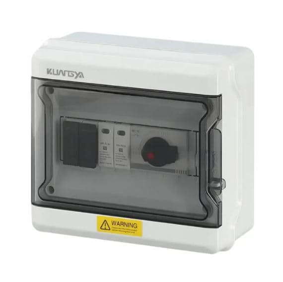
An insulation resistance test can help identify damaged insulation in PV string and combiner circuits before commissioning. The test boundary matters: the person testing must identify which conductors and components are connected, follow the approved test plan and equipment manuals, and record the conditions and result for each circuit. A single reading does not locate a fault or prove that the entire PV installation is ready to energize.
PV string inputs and the combiner output provide practical circuit boundaries for commissioning and troubleshooting. Testing individual circuits can help narrow an abnormal result before parallel connections conceal its location. Fluke describes insulation resistance testing on PV source circuits and combiner output circuits as part of commissioning. IEC 62446-1 covers the documentation, inspection and commissioning tests for grid-connected PV systems.
Identify the string or output cable, its drawing reference, termination points, and every connected device. Check the instructions for the modules, inverter, DC surge protective device, disconnect switch, monitoring electronics and insulation tester. Sensitive electronics or connected protective devices may require isolation before a test; never assume a combiner’s switch disconnects every part of the circuit. PV modules can generate voltage in daylight even when the inverter is off.
Only qualified personnel should work under an approved isolation and verification procedure, with instruments and personal protection appropriate to the installation. The applicable standard, equipment ratings and manufacturer instructions determine the test method, voltage, acceptance criteria and reconnection sequence. Do not apply an arbitrary value copied from another project.
Before testing, confirm the circuit boundary:
The boundary and any disconnections must follow the equipment manuals and the site procedure. This checklist is for planning and recording; it is not a substitute for the qualified tester’s switching and safety procedure.
Keep this record with the combiner box wiring diagram and as-built documentation. Verify the polarity of each string separately; insulation resistance and polarity answer different questions.
Stop commissioning the affected circuit. Confirm the test boundary and instrument setup, then investigate potential cable damage, moisture at cable entries, connector or termination problems, and connected components that may alter the reading. Compare like-for-like circuits only after accounting for their configuration and conditions. Record the cause and retest after correction.
An inverter’s insulation alarm can flag a problem, but it may not identify the faulty string. The PV combiner box configuration and its approved drawings help divide the investigation into manageable circuits.
Follow each manufacturer’s instructions. Do not expose connected electronics or protective devices to a test they are not rated to withstand.
No. The project commissioning plan also covers inspection and other required tests, including polarity and functional checks.
No. Apply the relevant edition of the standard, local requirements and the equipment manufacturer’s criteria to the actual installation.

