WengYang Industrial Zone Yueqing Wenzhou 325000
Work Hours
Monday to Friday: 7AM - 7PM
Weekend: 10AM - 5PM
WengYang Industrial Zone Yueqing Wenzhou 325000
Work Hours
Monday to Friday: 7AM - 7PM
Weekend: 10AM - 5PM
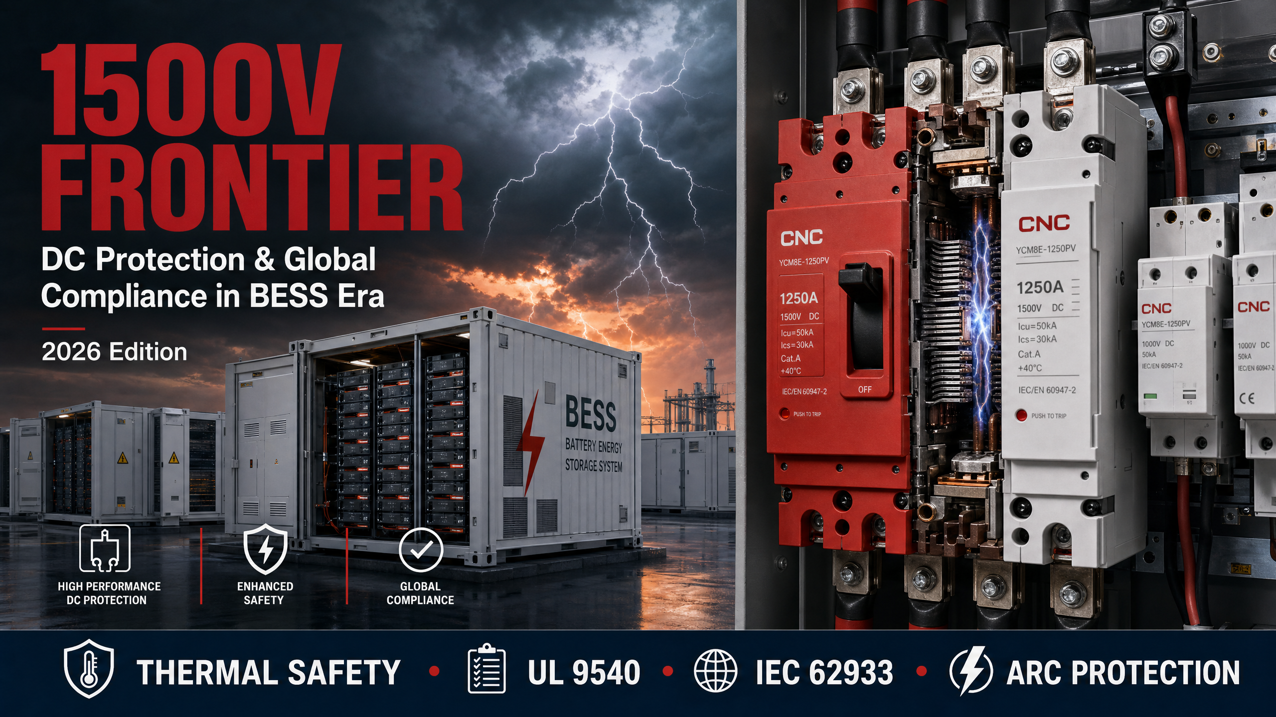
The global energy storage landscape has entered a transformative phase. As battery energy storage systems (BESS) proliferate across utility-scale installations, commercial facilities, and grid-integrated applications, the industry’s migration toward 1500V DC architectures has accelerated beyond projections. This voltage threshold—once considered ambitious—now represents the new baseline for efficiency-driven deployments, fundamentally reshaping protection requirements, compliance frameworks, and safety protocols across international markets.
The shift from 1000V to 1500V DC systems is not merely incremental optimization. By operating at higher voltages, BESS installations reduce current flow proportionally, yielding measurable gains in conductor sizing, thermal management, and conversion efficiency. Modern commercial and industrial energy storage configurations routinely step up to 1000V or 1500V DC to optimize round-trip efficiency, with the higher voltage tier delivering system-level cost reductions of 8-12% in balance-of-system components. citation
Yet this efficiency dividend introduces non-trivial protection challenges. Unlike alternating current, which naturally crosses zero twice per cycle and facilitates arc extinction, direct current maintains continuous polarity. At 1500V, fault arcs persist with extraordinary tenacity, demanding specialized interruption mechanisms that conventional AC-rated equipment cannot provide. The arc energy at these voltages can exceed 40 kJ in utility-scale combiner boxes, creating thermal hazards that require purpose-built arc quenching chambers and magnetic blowout systems. citation
The 2025 edition of AS/NZS 3008.1.1 now explicitly covers DC cables for circuits up to 1500V DC, reflecting the standard’s recognition that this voltage class dominates low-voltage DC applications including solar PV systems, battery storage, and EV charging infrastructure. citation This regulatory acknowledgment signals a broader industry consensus: 1500V is no longer experimental—it is operational reality.
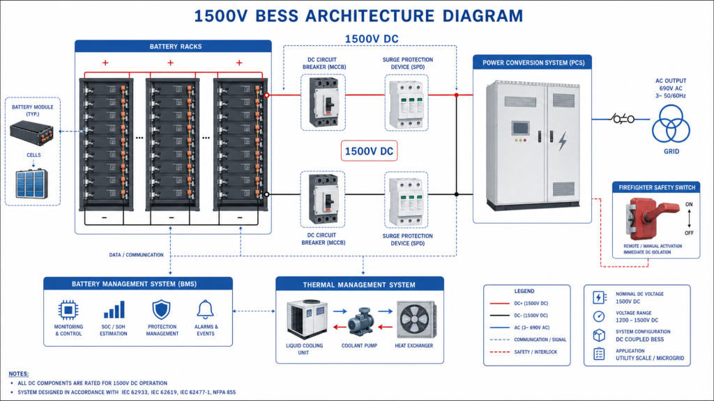
The protection of 1500V BESS installations requires a multi-layered approach that addresses fault detection, arc suppression, thermal runaway propagation, and emergency isolation. Each layer must function reliably under conditions that stress conventional electrical protection theory.
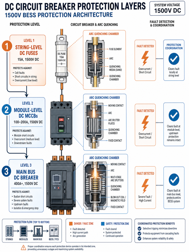
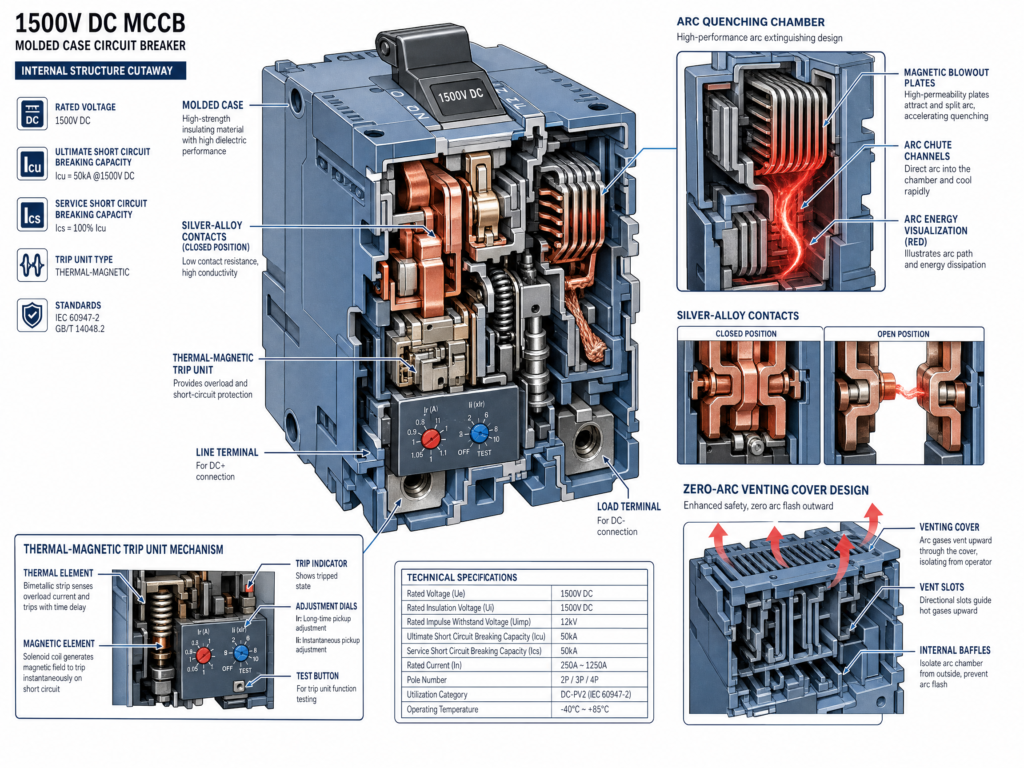
Modern 1500V DC molded case circuit breakers (MCCBs) represent a departure from their AC counterparts in fundamental ways. These devices incorporate engineered arc chambers with magnetic blowout plates and silver-alloy contacts to maintain reliable breaking performance under sustained DC fault conditions. The breaking capacity—typically rated between 10-20 kA depending on system fault levels—must be verified through IEC 60947-2 DC-PV category testing, which subjects the breaker to worst-case fault scenarios at full rated voltage. For a comprehensive understanding of DC circuit breaker selection methodology, refer to this practical guide to DC circuit breakers covering solar, battery, and EV systems. citation
Critical design features include:
Thermal-Magnetic Trip Units: Unlike purely magnetic trips, these hybrid mechanisms respond to both sustained overcurrent (thermal element) and instantaneous fault current (magnetic element), providing selectivity in protection coordination. For a 1500V combiner box with 200A bus rating, proper coordination requires gPV-rated DC fuses at string level (typically 15A, 1500V, 30kA breaking capacity) paired with a 200A DC MCCB at the main bus, achieving selectivity ratios exceeding 5.6:1 to meet IEC 60269-6 requirements. citation
Advanced Arc Quenching Chambers: The continuous nature of DC arcs demands specialized extinction mechanisms.
Pole Configuration Requirements: System grounding topology dictates breaker pole requirements. In ungrounded or floating DC systems common in utility-scale BESS, both positive and negative conductors must be simultaneously disconnected, requiring 2-pole minimum configuration. For grounded systems with midpoint earthing, single-pole disconnection of the ungrounded conductor may suffice, though redundancy considerations often drive 2-pole deployment regardless. A detailed technical guide with diagrams provides additional sizing and installation guidance for solar PV applications. citation
| Parameter | Specification Range | Selection Guideline | Verification Method |
|---|---|---|---|
| Rated Voltage | 1500V DC minimum | Must exceed system maximum voltage by 20% safety margin | Nameplate rating + IEC 60947-2 certification |
| Rated Current | 6A to 400A typical | ≥ String current × 1.25 (continuous rating) | Thermal derating calculation |
| Breaking Capacity (Icu) | 10-20 kA for BESS | Based on maximum prospective fault current at installation point | Short-circuit study required |
| Trip Characteristics | Thermal-magnetic or electronic | Thermal: overload protection; Magnetic: short-circuit protection | Coordination study with upstream/downstream devices |
| Pole Configuration | 1P, 2P, 3P, 4P | Determined by grounding topology (floating systems require 2P minimum) | System grounding diagram |
| Arc Quenching | Zero-arc venting preferred | Essential for containerized installations to prevent plasma ejection | Manufacturer test reports |
| Operating Temperature | -40°C to +85°C typical | Must cover ambient + self-heating in worst-case conditions | Thermal imaging verification |
| Certifications | IEC 60947-2 DC-PV category | Mandatory for PV/BESS applications; verify test voltage matches 1500V | Certificate review + traceability |
Operating at 1500V DC amplifies vulnerability to transient overvoltages from lightning strikes, switching operations, and grid faults. Modern surge protective devices (SPDs) for these systems must exhibit voltage protection ratings (VPR) below 2000V while maintaining sufficient energy dissipation capacity—typically 40 kA per mode for utility-scale installations. The SPD must also feature thermal disconnection mechanisms that prevent sustained follow-current in the event of device degradation, a failure mode that has caused multiple BESS fires in installations lacking this protection. citation
The proliferation of containerized BESS has elevated the importance of rapid disconnect capability for emergency responders. 1500V DC firefighter safety switches provide visible, lockable isolation points that enable first responders to de-energize DC strings without entering the container. In BESS applications, these switches serve dual purposes: facilitating thermal runaway containment by isolating affected battery strings and enabling safe access for maintenance operations. Proper installation requires placement external to the container with clear labeling and integration into the facility’s emergency response procedures. citation
The regulatory environment for 1500V BESS installations remains fragmented across jurisdictions, though convergence around core safety principles has accelerated in 2025-2026. Understanding the interplay between system-level standards, component certifications, and installation codes is essential for deployments targeting multiple markets.
| Region | Primary Standards | Voltage Coverage | Testing Requirements | Market Access |
|---|---|---|---|---|
| North America | UL 9540, UL 9540A, NFPA 855 | Up to 1500V DC | 3-level thermal runaway, system integration | Mandatory for permitting |
| European Union | IEC 62933-5-2, EN standards, CE marking | Up to 1500V DC | Safety, EMC, Battery Passport compliance | CE mark required |
| International | IEC 62933 series, IEC 60947-2 | Technology agnostic | Performance, safety, environmental impact | Global baseline |
| India | CEA Safety Regulations 2026 | Up to 1500V DC | Container design, spatial separation, fire training | Mandatory for grid-connected |
| China | GB/T standards, CQC certification | Up to 1500V DC | National testing protocols | CCC certification |
| Australia/NZ | AS/NZS 3008.1.1:2025, AS/NZS 5139 | Up to 1500V DC | DC cable sizing, installation safety | State-level enforcement |
| Standard | Scope | Key Requirements | Certification Status |
|---|---|---|---|
| UL 9540 | System-level safety for ESS | Component interaction testing, fault condition evaluation, thermal management verification | Mandatory for commercial/utility-scale projects |
| UL 9540A | Thermal runaway test method | Cell, module, and unit-level fire propagation testing | Required for UL 9540 certification |
| NFPA 855 | Installation requirements | Spatial separation, ventilation, explosion protection, emergency access | Enforced by fire authorities and AHJs |
| UL 1973 | Battery component safety | Individual battery assembly testing for stationary applications | Component-level prerequisite |
UL 9540 remains the cornerstone system-level safety standard for energy storage systems in North America. This comprehensive standard evaluates the interaction of all system components—batteries, inverters, controllers, thermal management systems—under both normal operation and fault conditions. Certification to UL 9540 is effectively mandatory for commercial and utility-scale BESS projects, serving as a prerequisite for permitting, utility interconnection agreements, and insurance underwriting. For detailed guidance on navigating the certification process, UL Solutions provides an official guide to battery energy storage regulatory compliance and testing and certification services. The standard’s 2025 revision incorporated enhanced requirements for DC arc fault detection and thermal propagation barriers, directly addressing failure modes observed in recent incidents. citation citation
UL 9540A provides the standardized test methodology for evaluating thermal runaway fire propagation. Critically, this testing must be completed at three levels—cell, module, and unit—yet many suppliers present only cell-level reports, leaving buyers unknowingly accepting incomplete documentation. Proper due diligence requires verification of all three test levels, as propagation behavior at the module and unit levels often diverges significantly from cell-level predictions. citation
NFPA 855 (Standard for the Installation of Stationary Energy Storage Systems) governs how UL 9540-certified products translate into safe real-world installations. The 2026 edition introduced significant updates including refined spatial separation requirements based on battery chemistry, enhanced ventilation specifications for container-based systems, and prescriptive guidance for explosion protection measures. The standard now mandates minimum separation distances between BESS enclosures and adjacent structures, with lithium-ion systems requiring greater clearances than lead-acid or nickel-cadmium chemistries. citation citation
The IEC 62933 series provides the global framework for grid energy storage systems, establishing requirements for design, safety, performance, and environmental impact across all storage technologies. IEC 62933-5-2 specifically addresses safety requirements for grid-integrated electrochemical energy storage systems, serving as the international counterpart to UL 9540. The standard emphasizes thermal protection as a critical safety element, aligning with UL 9540A’s focus on thermal runaway propagation. citation
For manufacturers targeting global markets, IEC 62933 certification ensures BESS compliance across diverse regulatory environments, complementing region-specific standards like UL 9540 in North America or CE marking requirements in the European Union. The standard’s technology-agnostic approach accommodates not only lithium-ion systems but also emerging chemistries and hybrid storage configurations, providing regulatory continuity as the technology landscape evolves. citation
The EU Battery Regulation entered force on February 18, 2024, and will fully replace the previous Battery Directive by August 2025. This comprehensive framework introduces mandatory requirements including CE marking for safety compliance, Battery Passports for supply chain transparency, and Extended Producer Responsibility (EPR) obligations for end-of-life management. For BESS manufacturers, compliance requires demonstrating conformity with harmonized safety standards, implementing digital product passports that track battery composition and lifecycle data, and establishing take-back systems for decommissioned systems. citation
The European Association for Storage of Energy (EASE) published updated Guidelines on Safety Best Practices in 2025, covering product design, site management, and emergency response protocols. These guidelines, while not legally binding, represent industry consensus on safety measures that exceed minimum regulatory requirements and are increasingly referenced in project financing agreements and insurance policies. citation
India’s Central Electricity Authority notified the Measures relating to Safety and Electric Supply Amendment Regulations in 2026, introducing a comprehensive safety framework for BESS installations. The regulations establish specific provisions for container design including explosion protection, forced ventilation, automated louvers, and ingress protection ratings. Spatial separation requirements are mandated based on battery chemistry, with prescriptive distances between BESS enclosures and nearby structures. The regulations also require state governments to ensure training of fire safety personnel for BESS-specific risks, with implementation guidelines issued by the Directorate General of Fire Services. citation
This regulatory development reflects India’s aggressive energy storage deployment targets, with peak power demand projected to rise from 289 GW in 2026-27 to 459 GW by 2035-36, necessitating substantial BESS capacity additions to maintain grid adequacy. citation
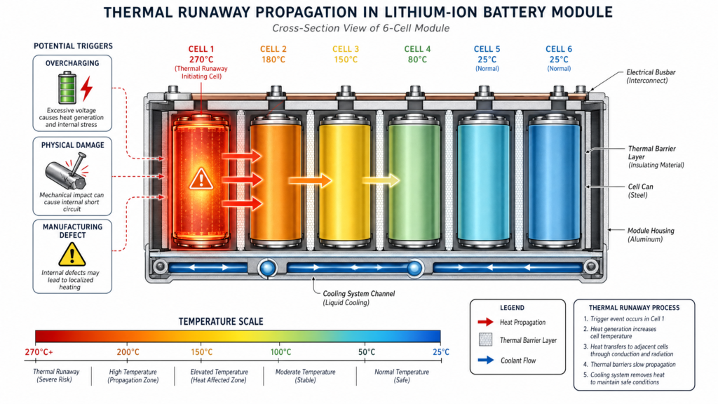
Figure 4: Thermal Runaway Propagation – Heat transfer from initiating cell (270°C) to adjacent cells, showing temperature gradient and propagation barriers
Thermal runaway remains the most consequential safety risk in lithium-ion BESS installations. This self-sustaining exothermic reaction occurs when overheating in one cell causes adjacent cells to fail in cascade, potentially resulting in fire or explosion. Triggers include overcharging, manufacturing defects, physical damage, or external heating from adjacent cell failures. citation
Recent incidents underscore the severity of this risk. The Gateway Energy Storage Facility fire in San Diego on May 15, 2024, involved approximately 15,000 nickel manganese cobalt lithium-ion cells and resulted in continued flare-ups for seven days following initial ignition. The Moss Landing BESS fire on January 16, 2025, necessitated evacuation of approximately 1,200 residents for 24 hours. Both incidents prompted extensive regulatory review and accelerated adoption of enhanced thermal management and fire suppression technologies. The EPA provides comprehensive guidance on BESS installation and incident response for communities and first responders. citation
Effective thermal runaway mitigation requires multiple concurrent approaches:
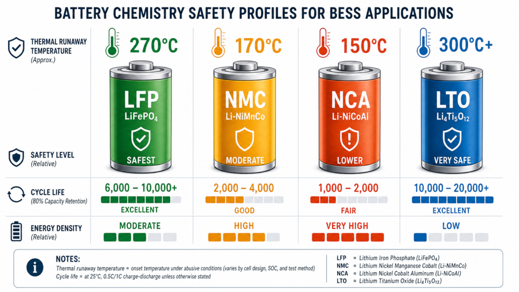
Battery Chemistry Selection: Lithium iron phosphate (LFP) chemistries exhibit superior thermal stability compared to nickel manganese cobalt (NMC) formulations, with thermal runaway initiation temperatures approximately 100°C higher. This inherent stability advantage has driven LFP’s market share gains in utility-scale BESS despite lower energy density.
| Chemistry | Thermal Runaway Temp | Energy Density | Cycle Life | Safety Profile | Primary Use Case |
|---|---|---|---|---|---|
| LFP (LiFePO₄) | ~270°C | 90-160 Wh/kg | 4,000-8,000 cycles | Excellent – most stable | Utility-scale, C&I storage |
| NMC (Li-NiMnCo) | ~170°C | 150-220 Wh/kg | 1,000-3,000 cycles | Moderate – requires robust BMS | High energy density applications |
| NCA (Li-NiCoAl) | ~150°C | 200-260 Wh/kg | 500-1,500 cycles | Lower – aggressive thermal management needed | EV applications, limited BESS use |
| LTO (Li₄Ti₅O₁₂) | >300°C | 50-80 Wh/kg | 10,000-25,000 cycles | Excellent – inherently safe | Frequency regulation, fast cycling |
Thermal Management Systems: Active liquid cooling systems maintain cell temperatures within optimal operating ranges (typically 15-35°C) while providing thermal buffering capacity to absorb heat from incipient failures before propagation occurs. Advanced systems incorporate immersion cooling, where cells are submerged in dielectric fluid, providing superior heat transfer coefficients and eliminating hot spots that can trigger thermal runaway. citation
Early Detection Systems: Multi-sensor arrays monitoring temperature, voltage, and off-gas composition enable detection of pre-runaway conditions minutes to hours before thermal propagation. Modern battery management systems (BMS) integrate these sensor streams with predictive algorithms that identify degradation patterns indicative of elevated risk, enabling preemptive isolation of affected modules. Battery Management Systems serve as the first line of defense, as detailed in this comprehensive battery safety guide.
Fire Suppression: Aerosol-based suppression systems designed specifically for lithium-ion fires have demonstrated superior performance compared to traditional water-based systems, which can exacerbate certain failure modes. These systems deploy potassium-based aerosols that interrupt combustion chemistry while cooling affected cells below propagation thresholds.
High-current BESS connectors represent a frequently underspecified element of 1500V system design, yet connector failures account for a disproportionate share of field reliability issues. Modern energy storage connectors must handle continuous currents up to 400A at voltages exceeding 1500V DC while maintaining contact resistance below 0.5 milliohms to prevent thermal degradation. citation
Critical specifications include:
IP2X Touch-Proof Safety: Prevents accidental contact with live conductors during maintenance operations, a mandatory requirement under most jurisdictions’ electrical safety codes for voltages exceeding 60V DC.
Thermal Management: Contact resistance directly determines the heat signature of battery racks. A 0.5 milliohm resistance at 400A continuous current generates 80W of heat per connection—multiplied across dozens of connections per rack, this represents a significant thermal load that must be managed to prevent accelerated degradation.
Mechanical Durability: Connectors must withstand thousands of mating cycles without degradation while maintaining electrical performance under vibration and thermal cycling conditions typical of containerized installations.
Arc flash hazards in 1500V DC systems differ fundamentally from AC equivalents due to the absence of current zero-crossings. DC arcs sustain longer, release more energy, and require higher incident energy ratings for personal protective equipment (PPE). For 1500V PV systems, minimum Category 2 PPE is standard for combiner box work, while BESS rack maintenance typically requires Category 3 or remote racking tools to maintain safe working distances. citation
Proper arc flash risk assessment requires calculating available fault current, arc duration based on protective device clearing times, and working distance. For installations exceeding 1 MW PV or 500 kWh BESS capacity, third-party arc flash studies by qualified electrical engineers are recommended, typically costing $3,000-$8,000 but providing defensible calculations for insurance and regulatory compliance. citation
The 1500V frontier represents current best practice, but the industry’s trajectory points toward further voltage escalation. Medium-voltage DC systems above 1500V are emerging in utility-scale applications, driven by continued efficiency optimization and the economics of ever-larger installations. These systems will require new protection paradigms, as existing low-voltage standards explicitly exclude voltages above 1500V DC. citation
Simultaneously, the regulatory environment continues rapid evolution. The convergence of safety standards across jurisdictions—evidenced by the alignment between UL 9540A and IEC 62933-5-2 on thermal propagation testing—suggests that global harmonization, while incomplete, is progressing. Manufacturers designing for international deployment can increasingly rely on core certifications that satisfy requirements across multiple markets, reducing compliance costs and accelerating deployment timelines.
The proliferation of BESS installations also drives continuous learning from operational experience. Each incident—whether minor thermal event or major fire—contributes data that informs standard revisions, protection system improvements, and emergency response protocols. The industry’s challenge is maintaining deployment momentum while incorporating these lessons without delay.
The migration to 1500V DC architectures in BESS installations represents rational engineering optimization, delivering measurable economic and performance benefits. Yet these advantages materialize only when accompanied by rigorous protection design, comprehensive compliance verification, and operational discipline that acknowledges the unique hazards of high-voltage DC systems.
Success in this environment requires moving beyond checkbox compliance toward genuine safety culture: specifying protection equipment based on verified performance rather than cost minimization, demanding complete certification documentation rather than accepting partial reports, designing for worst-case fault scenarios rather than typical operation, and maintaining emergency response capabilities proportionate to the hazards present.
The 1500V frontier is not a destination but a waypoint in the ongoing evolution of energy storage technology. The protection principles and compliance frameworks established today will shape the industry’s ability to scale safely toward the multi-gigawatt deployments required for deep grid decarbonization. Getting these fundamentals right now determines whether BESS achieves its promise as enabling infrastructure for the energy transition—or becomes constrained by safety incidents that erode public confidence and regulatory support.
The technical challenges are substantial but not insurmountable. The regulatory frameworks, while fragmented, are converging. The protection technologies exist and continue improving. What remains is execution: applying known solutions with the rigor that high-voltage DC systems demand, learning from failures without repeating them, and maintaining focus on safety as the industry scales toward its next order of magnitude.
For readers seeking additional technical depth on specific topics covered in this analysis, the following resources provide valuable complementary information:
Standards and Certification:
DC Protection and Circuit Breakers:
Thermal Runaway and Safety:
Compliance and Safety Guidelines:
Q: Why is 1500V becoming the standard for BESS installations instead of 1000V?
A: The migration to 1500V delivers 8-12% system-level cost reductions in balance-of-system components by reducing current flow proportionally. Lower current enables smaller conductor sizing, reduced thermal losses, and improved conversion efficiency. At utility scale, these savings compound across megawatt-hour installations, making 1500V the economically rational choice despite increased protection complexity.
Q: Can I use standard AC circuit breakers in a 1500V DC BESS system?
A: Absolutely not. AC circuit breakers lack the specialized arc quenching mechanisms required for DC fault interruption. DC arcs persist continuously without the natural zero-crossings that facilitate AC arc extinction. Using AC-rated breakers in DC applications creates severe fire hazards and violates all relevant safety standards. Only breakers certified to IEC 60947-2 DC-PV category at 1500V rating are acceptable.
Q: What is the difference between UL 9540 and IEC 62933?
A: UL 9540 is the North American system-level safety standard mandatory for commercial/utility BESS projects in the US and Canada. IEC 62933 is the international framework providing global baseline requirements. While both address system safety, UL 9540 includes specific testing protocols (like UL 9540A thermal runaway testing) tailored to North American regulatory requirements. IEC 62933 offers broader technology coverage and facilitates international market access. Many manufacturers pursue both certifications for global deployment.
Q: How do I calculate the required breaking capacity for a 1500V DC circuit breaker?
A: Breaking capacity (Icu) must equal or exceed the maximum prospective fault current at the breaker’s installation point. For BESS applications, this requires a short-circuit study considering:
For most utility-scale 1500V BESS installations, 10-20 kA breaking capacity suffices. Systems exceeding 1 MW or 500 kWh should engage qualified electrical engineers for formal arc flash and fault current studies.
Q: What PPE category is required for working on 1500V BESS equipment?
A: Minimum PPE requirements depend on the specific task:
Many operators mandate remote racking tools and de-energization protocols to eliminate arc flash exposure entirely. Always conduct site-specific arc flash hazard analysis per NFPA 70E or equivalent standards.
Q: Do I need thermal runaway testing at all three levels (cell, module, unit) for UL 9540A compliance?
A: Yes. Complete UL 9540A compliance requires testing at cell, module, and unit levels. Many suppliers present only cell-level reports, which is insufficient. Thermal propagation behavior at module and unit levels often diverges significantly from cell-level predictions due to:
Accepting incomplete documentation exposes buyers to unknown fire propagation risks and may void insurance coverage or violate permitting conditions.
Q: Which certifications are mandatory for deploying BESS in multiple international markets?
A: For global deployment, pursue this certification stack:
Component certifications (batteries, inverters, breakers) must align with system-level requirements. Engage certification bodies early in design phase to avoid costly redesigns.
Q: How does NFPA 855 affect BESS installation even if I have UL 9540 certification?
A: UL 9540 certifies the product’s safety; NFPA 855 governs how and where you install it. Key NFPA 855 requirements include:
Authorities Having Jurisdiction (AHJs) enforce NFPA 855 during permitting. Non-compliance blocks project commissioning regardless of product certifications.
Q: What is the EU Battery Passport and when does it become mandatory?
A: The EU Battery Passport is a digital record tracking battery composition, manufacturing origin, carbon footprint, and lifecycle data. It becomes mandatory for industrial and EV batteries >2 kWh starting February 2027. For BESS manufacturers, this requires:
Non-compliance blocks market access in EU member states after the enforcement date.
Q: What causes thermal runaway in BESS installations and how can it be prevented?
A: Thermal runaway triggers include:
Prevention strategies:
Q: How often should 1500V DC protection equipment be tested and maintained?
A: Recommended maintenance intervals:
High-utilization installations (>1 cycle/day) may require more frequent inspection. Maintain detailed service logs for insurance and regulatory compliance.
Q: What should emergency responders know about 1500V BESS installations?
A: Critical information for first responders:
Site emergency response plans must include facility-specific procedures, pre-incident planning with local fire departments, and regular joint training exercises.planning with local fire departments, and regular joint training exercises.
