WengYang Industrial Zone Yueqing Wenzhou 325000
Work Hours
Monday to Friday: 7AM - 7PM
Weekend: 10AM - 5PM
WengYang Industrial Zone Yueqing Wenzhou 325000
Work Hours
Monday to Friday: 7AM - 7PM
Weekend: 10AM - 5PM
Solar surge protection is the frontline defense for your renewable energy infrastructure. As solar PV systems increase in scale and complexity, their vulnerability to transient overvoltages—the silent killers of power electronics—grows exponentially. Implementing an effective solar surge protection strategy requires a multi-layered approach that accounts for both atmospheric lightning and grid-based transients.
As the global energy landscape undergoes a seismic shift toward decentralized generation, the proliferation of solar photovoltaic (PV) systems has reached an unprecedented scale. From massive utility-scale solar farms stretching across arid plains to sophisticated distributed rooftop arrays in densely populated urban centers, PV systems are the bedrock of the transition to a sustainable economy. Yet, despite their technical sophistication, these systems share a common, critical vulnerability: they are, by their very nature, exposed to the environment.
Electrical surges—transient overvoltages resulting from atmospheric discharges or utility-grid switching—represent the leading cause of premature power electronics failure in the solar industry. An unprotected inverter is not merely an asset at risk; it is a point of catastrophic failure. For system integrators, engineers, and facility managers, the correct deployment of Surge Protective Devices (SPDs) is the defining factor between a profitable, 25-year-lifespan installation and one plagued by recurring maintenance cycles and unplanned downtime. This white paper serves as an exhaustive technical guide to distinguishing between Type 1 and Type 2 SPDs, optimizing their placement within PV architecture, and mastering the engineering nuances that ensure long-term operational resilience.
To engineer a robust protection system, we must transcend the superficial understanding of “spikes” and dive into the electrodynamics of transient overvoltages.
Lightning is not a discrete event but a complex electromagnetic phenomenon involving high-energy discharge. When lightning strikes a structure’s external lightning protection system (LPS), the discharge current does not vanish; it seeks the path of least impedance to the earth. During this process, the structure’s grounding system experiences a massive potential rise, often exceeding several thousand volts.
Furthermore, we must account for inductive coupling. The rapid change in current ($di/dt$) associated with a lightning strike generates a powerful, expanding electromagnetic field. According to Faraday’s Law of Induction ($V = -L \cdot di/dt$), this field induces a secondary current in any conductive loop—including the DC cabling connecting PV modules to the inverter. Even if a lightning bolt strikes 100 meters away, the electromagnetic pulse (LEMP) can induce voltages in the DC array strings that far exceed the dielectric strength of the cables and the withstand voltage of the inverter’s internal DC-DC converters.
While lightning captures the headlines, switching transients are the silent, constant harbingers of hardware degradation. Within an electrical grid, the abrupt interruption of current in inductive loads—such as large utility transformers, neighboring motor drives, or even the grid-tied inverter itself during sudden shutdown sequences—causes voltage “ringing.”
These transients, characterized by high frequency and sub-microsecond rise times, travel through the AC supply lines. When they hit the inverter’s power conversion stage, they subject the Power MOSFETs and Insulated Gate Bipolar Transistors (IGBTs) to cumulative thermal and dielectric stress. Over time, these transients “wear down” the semiconductor lattice, leading to a phenomenon known as “infant mortality” in components that should have functioned for decades. The SPD’s role, therefore, is not just to survive a strike, but to act as a high-speed diversion path that clips these oscillations before they reach the delicate semiconductor junctions.
Understanding these electrodynamic threats is the first step in designing a reliable solar surge protection system. By anticipating how transients propagate through PV arrays, engineers can better select and deploy solar surge protection devices to mitigate premature hardware failure.
In the engineering of surge protection, compliance is not merely about certification labels; it is about ensuring that the device matches the specific energy environment of the PV string. The primary governing standard for photovoltaic surge protection is IEC 61643-31, which defines the test requirements and performance criteria for SPDs intended to be connected to the DC side of PV installations.
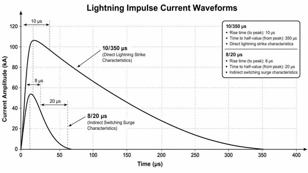
The fundamental distinction between Type 1 and Type 2 SPDs lies in the test waveform, which simulates the specific energy dissipation requirements of the device.
An engineer’s primary constraint when selecting an SPD is the $U_p$. This parameter represents the maximum voltage that will appear at the terminals of the SPD when it is conducting the nominal discharge current.
For an inverter with a maximum withstand voltage (dielectric strength) of, for example, 1500V, the $U_p$ of the SPD must be significantly lower—ideally under 1200V or 1300V—to provide a sufficient “safety margin.” The challenge is that $U_p$ is not a static number; it is dependent on the impulse current magnitude. A high-quality Type 2 SPD, such as those used in Kuangya’s industrial line, is engineered to maintain a low $U_p$ even under high-energy pulses, protecting the sensitive gate drivers and microprocessors within the solar inverter.
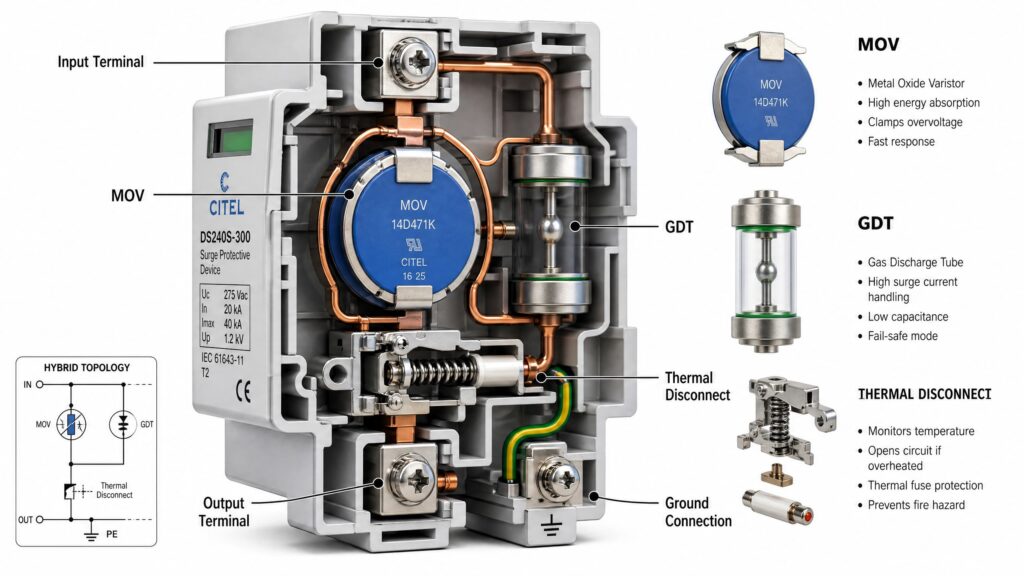
A common point of failure for sub-standard SPDs is the lack of a proper thermal disconnect mechanism. As an MOV (Metal Oxide Varistor) degrades due to repeated surges, it begins to draw a small “leakage current” even at normal operating voltage. This leakage generates heat within the ceramic disk.
A high-performance SPD must feature a thermally-activated disconnector that physically severs the connection to the grid before the device reaches a temperature that could ignite the surrounding enclosure. This is a critical requirement under IEC 61643-31; a compliant device must fail in a safe mode, preventing the SPD from becoming a fire hazard in the event of an end-of-life condition or a prolonged overvoltage event caused by utility instability.
A compliant solar surge protection device must fail in a safe mode. Utilizing high-quality thermal disconnectors within the solar surge protection module prevents fire hazards and ensures the safety of the entire PV array during end-of-life conditions.
When designing industrial-grade surge protection, the reliability of the device ultimately boils down to material science. A surge protective device is only as durable as the microscopic structures inside its core components. For PV systems operating under harsh, high-temperature environmental conditions, understanding these internal technologies is essential for procurement and system design.
The Metal Oxide Varistor is the foundational component of most Type 2 SPDs. At a microscopic level, an MOV is a ceramic-based semiconductor primarily composed of zinc oxide ($ZnO$) grains, interspersed with other metal oxide additives such as bismuth, antimony, and cobalt. The non-linear, voltage-dependent resistance of the MOV is formed at the boundaries between these grains, which act as microscopic, back-to-back semiconductor diodes.
Premium manufacturers utilize proprietary ceramic sintering and doping processes to widen the effective operating voltage window, ensuring that the device provides a low clamping voltage without sacrificing its peak current handling capability or accelerating aging.
While MOVs are excellent at clamping voltage rapidly, they suffer from continuous, albeit small, leakage currents that can accelerate aging over a 25-year lifespan. To mitigate this, engineers frequently utilize Gas Discharge Tubes.
A GDT consists of two or more electrodes hermetically sealed in a ceramic or glass cylinder filled with an inert gas (such as argon or neon) at a specific pressure.
To achieve maximum reliability on the vulnerable DC side of a solar array, advanced designs employ a Hybrid Technology that integrates both MOVs and GDTs within a single modular cartridge.
In a typical hybrid configuration, the MOV and GDT are connected in series between the active DC lines (positive or negative) and the earth (PE). The GDT isolates the MOV from the DC voltage during normal operation, which completely eliminates standing leakage current. When a surge event happens, the voltage divides across both components. The MOV reacts instantly to clamp the rising edge of the transient, while the GDT follows, providing a robust, low-impedance path for the bulk of the energy.
This synergistic approach dramatically extends the operational lifespan of the surge protection module, making it highly resistant to the elevated ambient temperatures found in rooftop junction boxes and inverter enclosures.
Designing a robust solar surge protection network involves more than selecting components; it requires a holistic view of the system’s architecture. A properly cascaded solar surge protection model provides a buffer that absorbs transients before they reach the inverter’s critical power stages.
When evaluating solar surge protection requirements, engineers must consider the specific environmental risk profile of the installation site.
Selecting the correct surge protection specification is only half the battle; the strategic placement and system-level integration are where the resilience of a solar PV installation is truly defined. A design that ignores the nuances of DC string cabling and grounding impedance is fundamentally incomplete.
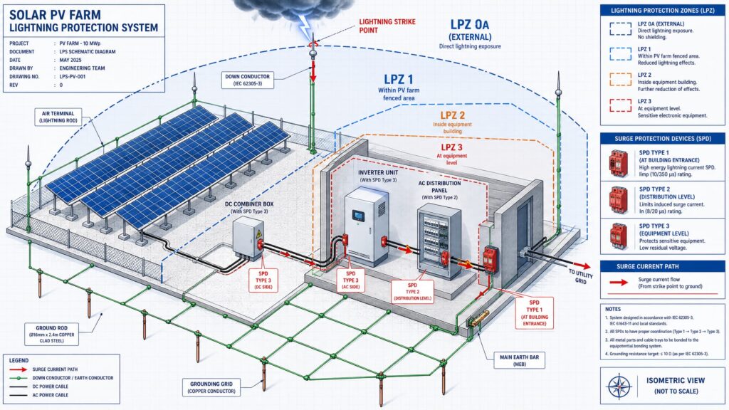
In high-risk environments—such as large-scale utility solar farms situated in mountainous regions or areas with high isokeraunic (lightning) levels—a single-stage SPD is rarely sufficient. Instead, we implement a Cascaded Protection Architecture.
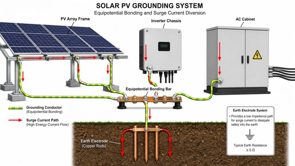
The efficacy of an SPD is entirely tethered to the equipotential bonding of the entire site. An SPD does not “delete” a surge; it redirects it. If the impedance of your grounding system is high, the energy has nowhere to go but into your equipment.
The efficacy of any solar surge protection strategy is inherently tied to the quality of the grounding system. Integrating equipotential bonding with your solar surge protection devices ensures that transient energy is safely diverted, preventing potential differences that could damage sensitive inverter components.
One of the most frequent engineering oversights is the creation of large cable loops in the DC string wiring. When lightning strikes, a large loop acts like an antenna. According to electromagnetic induction principles, the voltage induced in a loop is directly proportional to the area it encloses.
The most common “field failure” in surge protection is not the device itself, but the way it is wired. There is a fundamental rule in protection engineering: The 0.5-Meter Rule.
The total lead length (the distance from the SPD connection point to the DC lines, plus the distance from the SPD to the grounding point) should be kept under 500mm. Why? Because every 10cm of conductor adds approximately 100nH of inductance ($L$). Under a fast-rising lightning pulse with a rate of $di/dt$ in the kiloamperes-per-microsecond range, this inductance creates a significant voltage drop ($V = L \cdot di/dt$).
If you use a 2-meter wire to connect an SPD, the SPD might show a nominal clamping voltage of 2.0kV on its datasheet, but the inverter at the end of those long wires will actually experience a surge peak of 4.0kV or more. Keeping leads short is the most cost-effective way to improve system safety.
In modern utility-scale and commercial PV assets, the philosophy of “replace on failure” is increasingly obsolete. With the rising cost of site visits and the imperative to minimize downtime, the industry is transitioning toward predictive, condition-based maintenance. A premium SPD is not just a passive component; it is an active diagnostic tool.
The internal MOV degrades progressively. In its early life, it offers a near-perfect short circuit to transients. As the material lattice fractures due to accumulated energy pulses, the leakage current increases linearly, eventually leading to a drop in the device’s clamping efficacy.
For large-scale solar plants, visual inspection is impossible for every combiner box. This is where Remote Signaling Contacts become vital.
Kuangya-grade SPDs feature potential-free changeover contacts. These are integrated into the plant’s centralized Monitoring and Data Acquisition (SCADA) system. When the internal health of the SPD drops below a critical threshold or the thermal fuse triggers, the device sends a discrete signal to the central control room. This allows operations managers to dispatch a maintenance team with the specific replacement module before a system-wide failure occurs. This predictive approach is the hallmark of modern, bankable renewable energy projects.
In summary, effective solar surge protection is a critical component of every bankable PV project. By treating solar surge protection as a core engineering discipline, developers can guarantee the long-term energy yields of their solar infrastructure. Ultimately, investing in robust solar surge protection is a fundamental engineering requirement.
Ultimately, investing in robust solar surge protection is a fundamental engineering requirement that safeguards your energy yield.
Protecting a solar PV system is an investment in long-term yield. As the industry pushes toward higher system voltages—1500V DC and beyond—the margins for electrical error are shrinking. The vulnerability of power electronics to atmospheric and switching transients is a physical reality that cannot be negotiated away; it must be engineered away.
By mastering the technical distinction between Type 1 and Type 2 devices, adhering to the physical laws governing induction and grounding, and adopting a predictive lifecycle management strategy, project owners can harden their assets against the inevitable fluctuations of the grid and the environment.
A solar array is a 25-year financial instrument. Surge protection, when designed and installed with precision, ensures that this instrument maintains its performance, reliability, and profitability throughout its entire lifecycle.
| Feature | Type 1 SPD | Type 2 SPD |
| Primary Standard | IEC 61643-31 | IEC 61643-31 |
| Test Waveform | $10/350 \mu s$ | $8/20 \mu s$ |
| Lightning Exposure | High (Direct/External LPS) | Moderate (Induced/Switching) |
| Core Technology | Reinforced MOV/Spark Gap | High-Performance MOV |
| Placement | DC Combiner/Main Board | Inverter Input |
| Monitoring | Visual + Remote | Visual Standard |
Disclaimer: This guide is intended for educational purposes and provides a high-level engineering overview. All site designs must comply with local electrical codes, national safety standards, and manufacturer-specific installation guidelines. Always perform a site-specific risk assessment to determine the necessity of external lightning protection and the appropriate surge protection topology.
Type 1 SPD is designed to handle direct lightning strikes (10/350 μs waveform) and is installed at the service entrance.
Type 2 SPD is designed for induced surges and switching transients (8/20 μs waveform) and is installed in distribution boards.
In solar PV systems, Type 1 is used when there is an external lightning protection system, while Type 2 is the standard protection inside most PV combiner boxes and inverters.
No. Type 2 SPD cannot fully replace Type 1 SPD.
Type 2 SPD protects against indirect surges, but it is not designed to withstand direct lightning energy levels.
If the installation is in a high lightning-risk area or has external lightning protection (LPS), a Type 1 or Type 1+2 combined SPD is required.
SPDs should be installed in a cascaded protection layout:
This ensures multi-layer surge protection from grid to device level.
If the cable between SPD and equipment is too long, the protection performance decreases significantly.
Even a few meters of cable can create inductive voltage spikes, which may bypass the SPD protection.
👉 Best practice: keep lead length under 0.5 meters whenever possible.
The selection depends on three key factors:
General guideline:
Yes. SPDs are consumable protection devices.
They degrade after repeated surge events and should be checked regularly.
Most SPDs include a visual indicator:
In high lightning areas, periodic inspection is strongly recommended.
Are you ready to optimize your project’s surge protection?
Our technical team at Kuangya provides detailed configuration support for commercial and utility-scale installations. From calculating the temperature-compensated Maximum Continuous Operating Voltage ($U_{cpv}$) to providing custom CAD layouts for cascading protection, we are here to ensure your solar infrastructure is built to last.
Contact our engineering support team today to review your project schematics and secure your renewable energy investment.
