WengYang Industrial Zone Yueqing Wenzhou 325000
Work Hours
Monday to Friday: 7AM - 7PM
Weekend: 10AM - 5PM
WengYang Industrial Zone Yueqing Wenzhou 325000
Work Hours
Monday to Friday: 7AM - 7PM
Weekend: 10AM - 5PM
RCBO (Residual Current Breaker with Overcurrent) | Safe & Reliable Kuangya
Correct RCBO wiring is essential for ensuring both residual-current protection and overcurrent protection work as intended. Even the highest-quality RCBO cannot provide reliable protection if it is wired incorrectly.
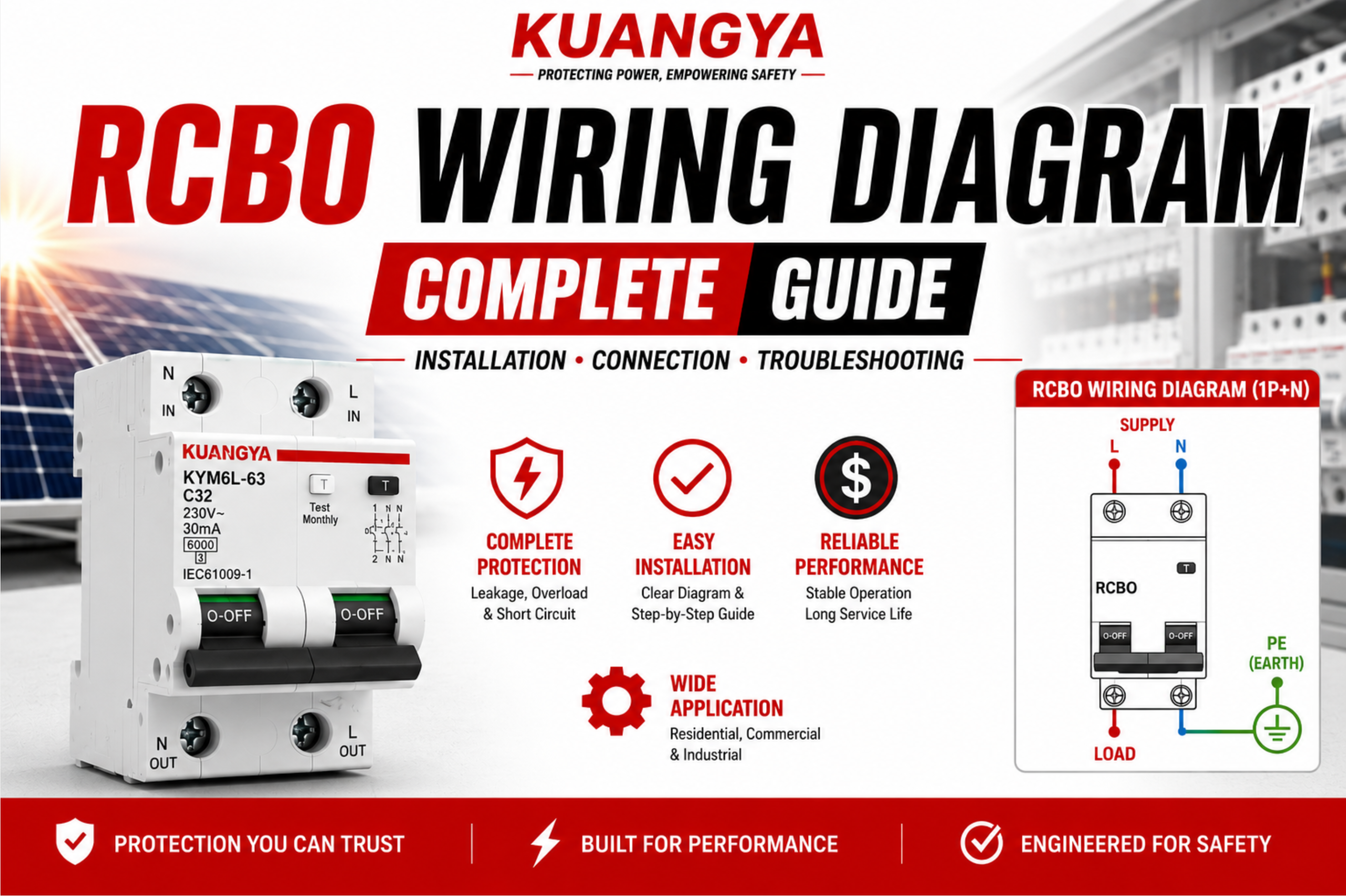
An RCBO (Residual Current Breaker with Overcurrent Protection) combines the functions of an RCCB and an MCB into a single device. It protects electrical circuits against earth leakage, overloads, and short circuits while helping isolate faults quickly and safely.
Whether you are installing a residential consumer unit, commercial distribution board, or industrial electrical panel, understanding the correct RCBO wiring diagram is critical for safety, compliance, and system reliability.
An RCBO wiring diagram shows how the line (L) and neutral (N) conductors pass through the RCBO while the protective earth (PE) conductor bypasses the device. Correct wiring ensures the RCBO can accurately detect residual current imbalances and disconnect the circuit during earth-fault, overload, or short-circuit conditions.
An RCBO wiring diagram is a visual representation showing how the RCBO should be connected within an electrical system.
It identifies:
The wiring diagram serves as a guide for installers and maintenance personnel, helping ensure that the device functions correctly after installation.
Without proper wiring, an RCBO may fail to trip during a leakage fault, trip unexpectedly during normal operation, produce false leakage indications, or lose effective protection capability.
Understanding the wiring diagram before installation helps avoid costly troubleshooting later.
Many electrical faults blamed on defective RCBOs are actually caused by incorrect wiring practices.
An RCBO continuously compares the current flowing through the line conductor with the current returning through the neutral conductor. Under normal conditions, these currents are equal.
When a fault occurs and current leaks to earth, the balance is disturbed. The RCBO detects this difference and disconnects the circuit.
Incorrect wiring can prevent this process from working correctly.
Potential consequences include:
Because RCBOs combine multiple protection functions in one device, proper wiring is essential to achieving the protection level expected by electrical standards.
RCBO (Residual Current Breaker with Overcurrent) | Safe & Reliable Kuangya
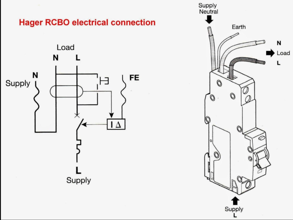
Before wiring an RCBO, it is important to understand the terminal markings.
| Terminal | Function |
|---|---|
| L IN | Incoming line conductor |
| N IN | Incoming neutral conductor |
| L OUT | Outgoing line conductor |
| N OUT | Outgoing neutral conductor |
| PE | Protective earth connection |
| TEST | Internal test circuit |
Different manufacturers may use different layouts, so always refer to the specific wiring diagram supplied with the device.
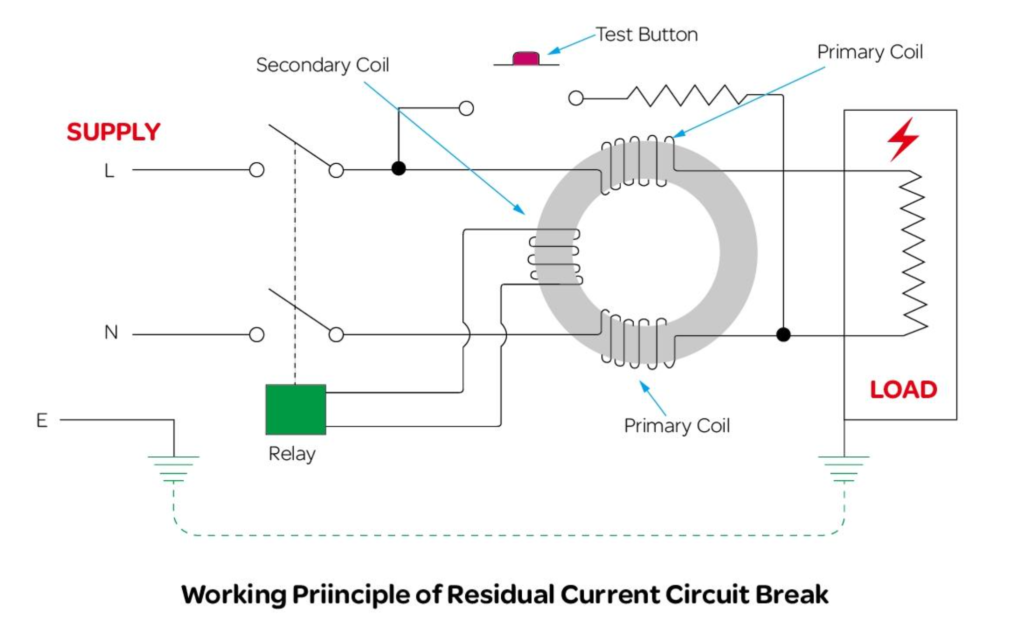
Inside every RCBO is a differential current transformer.
The device continuously monitors the current flowing through both the line and neutral conductors.
Under normal conditions:
During an earth fault:
This detection method allows RCBOs to respond quickly to potentially dangerous fault conditions.
Not all RCBO installations use the same wiring arrangement. The correct configuration depends on the electrical system, the number of phases, and the protection requirements of the installation.
The most common configurations include:
The most common option for residential installations.
Applications:
Advantages:
Two-pole RCBOs disconnect both line and neutral conductors simultaneously.
They are frequently used where complete circuit isolation is required.
Four-pole RCBOs are designed for three-phase systems.
Applications include:
Single-phase RCBOs are commonly used in residential and light commercial installations.
Typical applications include:
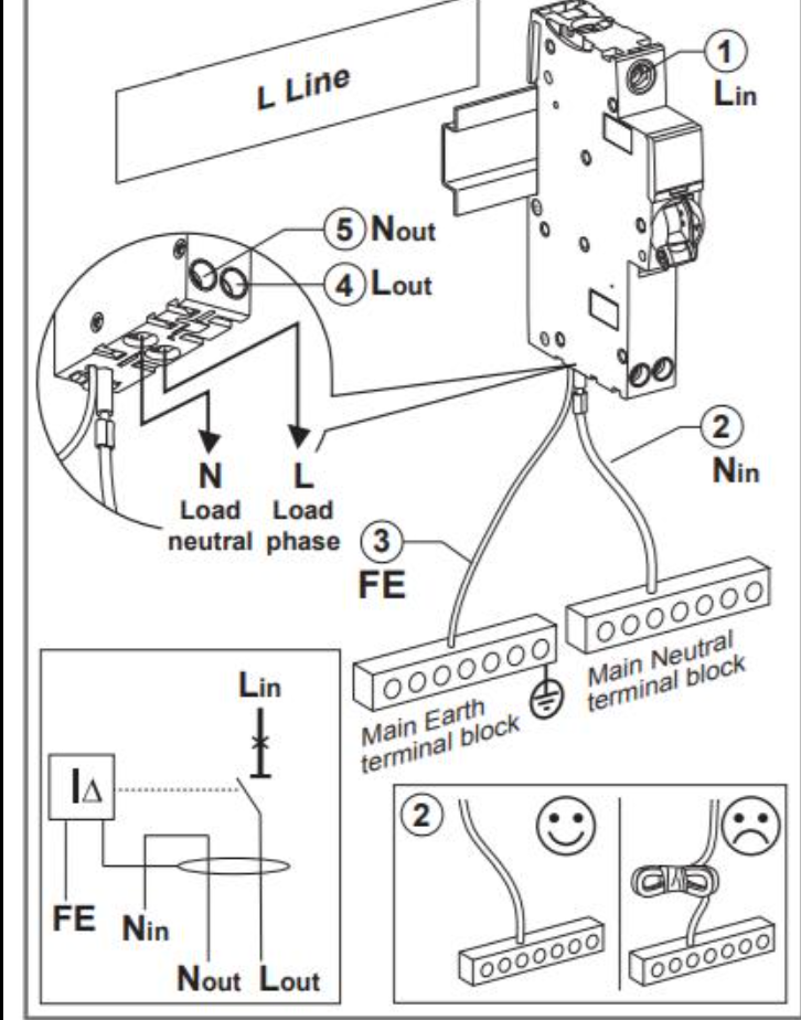
[Insert Single-Phase Wiring Diagram Here]
A 1P+N RCBO is one of the most commonly installed RCBO configurations.
Applications include:
Benefits include:
Two-pole RCBOs disconnect both phase and neutral conductors simultaneously.
Applications include:
Three-phase RCBOs are used in commercial and industrial installations.
Applications include:
A typical four-pole RCBO protects:
Caption: Four-pole RCBO protecting a three-phase electrical system.
Electrical wiring colors vary between countries, but proper conductor identification is essential for safe installation.
| Conductor | IEC Color |
|---|---|
| L1 | Brown |
| L2 | Black |
| L3 | Grey |
| Neutral | Blue |
| Earth | Green/Yellow |
Correct conductor identification helps reduce installation errors and simplifies maintenance.
Always verify local regulations before installation.
Switch off the main supply and verify that all circuits are de-energized.
Install the RCBO securely on the DIN rail.
Connect:
Connect:
Connect all earth conductors directly to the earth bar.
Never route earth conductors through the RCBO.
Press the TEST button to verify correct operation.
The RCBO should trip immediately.
Installing an RCBO is only part of the process. Testing is equally important.
Most RCBOs include a built-in TEST button.
Pressing the button creates an artificial leakage current.
A properly functioning RCBO should trip immediately.
Verify:
This can help identify:
Incorrect installation is one of the leading causes of RCBO problems.
Sharing neutrals between multiple circuits often causes nuisance tripping.
The neutral conductor must return through the same RCBO that supplies the circuit.
Not all RCBOs support reverse feeding.
Neutral-to-earth connections downstream of the RCBO may cause immediate tripping.
[Insert Wiring Mistakes Illustration Here]
Unexpected tripping is one of the most common questions electricians encounter.
Possible causes include:
Damaged insulation or faulty equipment may allow current to flow to earth.
A shared neutral can create current imbalances.
Outdoor equipment and damp environments can introduce leakage currents.
Faulty appliances frequently cause nuisance tripping.
Some applications require:
Using the wrong type can cause operational issues.
| Possible Cause | Recommended Check |
|---|---|
| Shared neutral | Inspect neighboring circuits |
| Earth leakage | Test insulation resistance |
| Incorrect wiring | Verify terminal connections |
| Damaged equipment | Disconnect loads individually |
| Neutral fault | Check neutral continuity |
Many problems can be identified simply by comparing the installation with the original wiring diagram.
| Feature | RCBO | RCCB |
|---|---|---|
| Leakage Protection | Yes | Yes |
| Overload Protection | Yes | No |
| Short-Circuit Protection | Yes | No |
| Requires Separate MCB | No | Yes |
An RCCB installation normally requires a separate MCB.
An RCBO combines both functions into a single device.
| Feature | RCBO | MCB |
|---|---|---|
| Leakage Detection | Yes | No |
| Overload Protection | Yes | Yes |
| Short-Circuit Protection | Yes | Yes |
An MCB cannot detect earth-leakage faults.
An RCBO provides additional protection against leakage currents.
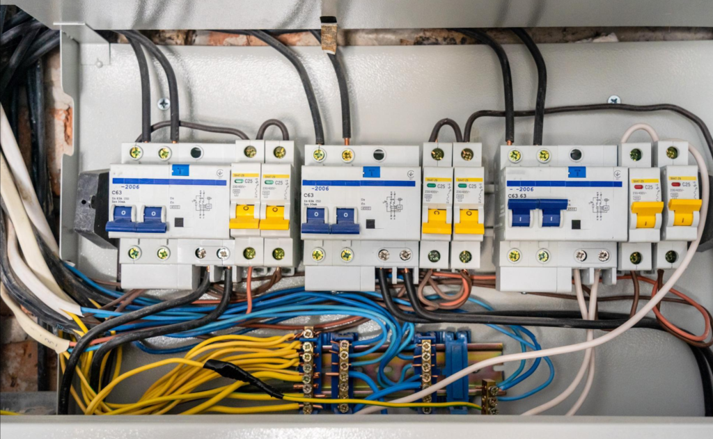
RCBOs are commonly installed inside distribution boards to provide individual circuit protection.
Benefits include:
Many modern distribution boards now use RCBOs on every outgoing circuit rather than relying on a single RCCB protecting multiple circuits.
Electric vehicle charging installations often require dedicated RCBO protection.
When wiring an EV charger:
Type A and Type B RCBOs are commonly specified depending on charger design.
[Insert EV Charger RCBO Wiring Diagram Here]
Solar photovoltaic systems often include inverters that generate complex current waveforms.
When wiring RCBO protection for solar applications:
[Insert Solar RCBO Wiring Diagram Here]
Choosing the correct RCBO involves more than selecting the right current rating.
Common ratings include:
| Sensitivity | Typical Application |
|---|---|
| 10mA | Enhanced personal protection |
| 30mA | Standard personnel protection |
| 100mA | Equipment protection |
| 300mA | Fire protection |
Typical values include:
Depending on the load characteristics, installers may choose:
Correct selection is particularly important for EV chargers, solar systems, battery storage systems, and inverter-driven equipment.
✓ Line conductor connected correctly
✓ Neutral conductor connected correctly
✓ Earth conductor bypasses RCBO
✓ No shared neutrals
✓ Correct terminal torque
✓ Functional test completed
✓ Device rating matches circuit requirements
✓ Manufacturer instructions followed
A properly wired RCBO provides reliable protection against earth leakage, overloads, and short circuits while helping improve overall electrical safety.
Whether installing a residential 1P+N RCBO, a commercial two-pole RCBO, or a three-phase four-pole RCBO, the fundamental principle remains the same: all current-carrying conductors must pass through the RCBO, while the protective earth conductor must remain outside the sensing circuit.
Understanding and following the correct RCBO wiring diagram helps reduce installation errors, improve system reliability, and ensure compliance with electrical safety standards.
Connect the incoming line and neutral conductors to the supply terminals and connect the outgoing load conductors to the load terminals. The earth conductor should connect directly to the earth bar.
Yes. Both line and neutral conductors must pass through the RCBO for residual-current detection to work correctly.
Common causes include shared neutrals, incorrect neutral routing, earth leakage faults, or wiring mistakes.
Most single-phase RCBOs require both line and neutral conductors to operate correctly.
No. Each RCBO-protected circuit should have its own dedicated neutral conductor.
Some RCBOs support reverse feeding, while others do not. Always check the manufacturer’s instructions.
No. An RCBO already provides overload and short-circuit protection.
A 1P+N RCBO typically switches the phase conductor and monitors the neutral, while a two-pole RCBO disconnects both conductors simultaneously.
The required RCBO type depends on the charger design and local regulations. Type A and Type B RCBOs are commonly used.
Most manufacturers recommend pressing the TEST button periodically to verify proper operation.
RCBO (Residual Current Breaker with Overcurrent) | Safe & Reliable Kuangya
