WengYang Industrial Zone Yueqing Wenzhou 325000
Work Hours
Monday to Friday: 7AM - 7PM
Weekend: 10AM - 5PM
WengYang Industrial Zone Yueqing Wenzhou 325000
Work Hours
Monday to Friday: 7AM - 7PM
Weekend: 10AM - 5PM

It’s 8 AM on a Monday morning. Dave, the facility manager for a sprawling logistics center, is reviewing his weekend reports when the call comes in. The solar array on his roof—a 500 kWp system that was supposed to be a flagship of the company’s green initiatives—is underperforming. In fact, a third of the array is completely offline. The monitoring software is screaming with inverter fault codes. A storm had rolled through the area on Saturday, but it wasn’t a direct hit; just a routine summer thunderstorm. Yet, the financial and operational fallout was anything but routine. The initial diagnosis from the O&M contractor is grim: multiple inverter power stages are fried, and the repair estimate is already in the tens of thousands, not including the lost energy production.
Dave’s situation is a common, and costly, reality for commercial and industrial solar stakeholders. While solar assets are celebrated for their reliability, they are uniquely vulnerable to a pervasive threat that is often underestimated in system design: transient overvoltages. We tend to think of storm damage in terms of direct, catastrophic lightning strikes, but the reality is far more insidious. According to an extensive analysis of solar project insurance claims, lightning and the associated electrical surges are one of the leading causes of damage, responsible for nearly 10% of all natural catastrophe incidents.
The financial sting is what truly brings the risk into focus. The average insurance claim for lightning-related damage to a solar project is a staggering $73,394. For a business owner, that’s a significant and unwelcome budget variance. For an installer, it’s a potential blow to their reputation. For Dave, it’s a week of operational headaches and a difficult conversation with his CFO. What he didn’t realize was that the storm on Saturday was just the final blow. His system had been silently absorbing smaller, unseen electrical surges for months, leading to a slow degradation of its sensitive electronic components. The thunderstorm was simply the event that pushed the already-weakened system over the edge. This is the story of the storm you don’t see coming—a story of silent, cumulative damage that proper surge protection is designed to prevent.
The vulnerability of a commercial solar array is a matter of physics. Large, interconnected metallic structures spread over a vast area, combined with extensive DC and AC cabling, create a massive antenna for atmospheric and electrical disturbances. While a direct lightning strike is the most dramatic example of a transient overvoltage event, it is by no means the only, or even the most common, threat. The vast majority of damage to solar inverters, combiners, and monitoring equipment comes from two less obvious sources: induced surges and switching transients.
The result of these events is a spectrum of damage. At one end is the immediate, catastrophic failure of an inverter, placing it out of service instantly. In the middle is intermittent-faulting, where an inverter trips offline and may or may not restart, causing diagnostic nightmares for O&M teams. At the other end is the slow, invisible erosion of performance as components like bypass diodes and power semiconductors are weakened, leading to a gradual loss of energy yield that can be difficult to pinpoint but significantly impacts the system’s financial returns over its lifetime. Without a systematic approach to protection, your high-tech solar asset is essentially a sitting duck.
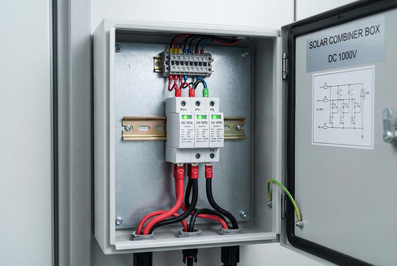
The traditional approach to surge protection has often been reactive or piecemeal—perhaps an SPD at the main AC service entrance, if at all. This is fundamentally inadequate for the complex, distributed nature of a commercial PV system. Effective protection is not about a single device, but about creating a coordinated, multi-stage defense system designed to manage and divert transient energy at every critical point. This is the core of our engineering philosophy.
The principle is called “cascading” or coordinated protection. It involves placing SPDs in a staged manner to systematically reduce the voltage of a surge as it travels through the system.

To implement this strategy effectively requires a new class of SPD that goes beyond legacy standards. Many SPDs on the market are rated as either Type 1 (designed for high-energy events, like direct lightning, characterized by a 10/350µs waveform) or Type 2 (designed for lower-energy, faster switching surges, characterized by an 8/20µs waveform). The problem is that a PV system is exposed to both.
Our solution is a premier Type 1+2 Hybrid SPD. This device incorporates a robust, high-capacity Metal Oxide Varistor (MOV) network capable of handling the immense energy of a 10/350µs impulse, while also having the low clamping voltage needed to protect against the faster 8/20µs transients. By using a single, advanced device at each stage, we eliminate the coordination problems that can arise from mixing different types of SPDs and provide comprehensive protection against all forms of overvoltage, from the grid to the panel.
This engineered system transforms surge protection from a compliance checkbox into a proactive strategy for asset preservation and financial assurance.
Not all SPDs are created equal. For technical professionals—engineers, designers, and installers—the datasheet is where credibility is won or lost. An effective SPD is defined by its ability to withstand massive surge currents while limiting the residual voltage passed to the equipment it’s protecting. Below are the key specifications for our DC and AC Type 1+2 Hybrid SPDs, designed specifically for the demanding environment of commercial solar applications.
DC Solar SPD – Series PV-Pro
| Parameter | Specification | Why It Matters |
|---|---|---|
| SPD Type | Type 1 + Type 2 (per IEC/EN 61643-31) | A single device handles both high-energy lightning (10/350µs) and switching (8/20µs) surges, simplifying design and ensuring full protection. |
| Max. PV Voltage (Vpv) | 600V / 1000V / 1500V DC | Models available to match the system voltage of any commercial or utility-scale project, ensuring proper application. |
| Max. Continuous Operating Voltage (MCOV) | > 1.2 x Vpv | A high MCOV prevents premature aging or “leaking” of the SPD under normal operating voltage variations, ensuring longevity. |
| Impulse Discharge Current (Iimp, 10/350µs) | 12.5 kA | This is the critical measure of a Type 1 SPD. Our 12.5 kA rating meets stringent standards for front-line lightning protection. |
| Nominal Discharge Current (In, 8/20µs) | 20 kA | Demonstrates the device’s ability to handle repeated, lower-energy surges without degrading, protecting against switching transients. |
| Voltage Protection Rating (VPR) / Up | < 4.0 kV (for 1000V model) | This is arguably the most important spec. A lower VPR means less surge voltage reaches your inverter. Our low VPR ensures we protect equipment where others fail. |
| Response Time | < 25 nanoseconds | Faster than a lightning bolt can propagate through your system. This near-instantaneous reaction is what prevents damage. |
| Short-Circuit Rating (SCCR) | 50 kA | The SPD must survive the worst-case fault current of your system without becoming a hazard itself. |
| Status Indication | Visual LED + Remote Contact | Allows at-a-glance verification of protection status and integration with monitoring systems for proactive maintenance. |
| Certifications | UL 1449 Ed.5, IEC 61643-31, TUV, CE | Independent third-party verification that the device meets the highest international safety and performance standards. |
AC Solar SPD – Series Grid-Guard
| Parameter | Specification | Why It Matters |
|---|---|---|
| SPD Type | Type 1 + Type 2 (per IEC/EN 61643-11) | Provides comprehensive protection on the AC side against both utility-grid and facility-originated transients. |
| Nominal System Voltage | 120/208V, 277/480V, 3-phase | Configurable for any commercial or industrial grid connection scenario in North America and international markets. |
| Max. Continuous Operating Voltage (MCOV) | 320V / 680V (L-N) | Ensures the SPD remains stable under utility voltage variations and temporary overvoltage conditions without false tripping. |
| Impulse Discharge Current (Iimp, 10/350µs) | 25 kA per phase | Higher capacity than DC side due to the proximity to grid-side lightning and fault events. Protects the entire AC distribution system. |
| Nominal Discharge Current (In, 8/20µs) | 40 kA per phase | Robust capacity for repeated switching surges from motors, drives, and grid operations. |
| Voltage Protection Rating (VPR) / Up | < 1.5 kV (for 277V system) | Keeps surge voltages well below the damage threshold of sensitive inverter output stages and building electrical systems. |
| Connection Type | 3-phase + Neutral + Ground (3+1) | Comprehensive protection across all conductors, preventing surge energy from finding an unprotected path. |
| Enclosure Rating | NEMA 4X / IP65 | Suitable for outdoor and harsh industrial environments, ensuring long-term reliability. |
| Status Indication | Visual LED + Audible Alarm + Remote Contact | Multi-level notification system for immediate awareness of protection status and end-of-life indication. |
| Certifications | UL 1449 Ed.5, IEC 61643-11, CSA, CE | Full compliance with North American and international standards for AC surge protection. |
These are not generic commodity devices. These are precision-engineered protection systems with performance characteristics that have been validated through rigorous testing and real-world deployment.
Let’s return to Dave and his distribution center. After the initial lightning damage, the facility management team made the decision to implement a comprehensive surge protection upgrade. Here’s what that looked like, and more importantly, what the measurable outcomes were.
The Initial Damage Assessment (Pre-SPD Installation):
The damage was not just financial. The operational disruption, the time spent coordinating repairs, and the uncertainty about future events created significant stress for the management team. Dave was spending 15-20 hours per week dealing with contractors, insurance adjusters, and explaining the situation to upper management.
The Protection Solution (Post-SPD Installation):
Working with a qualified electrical contractor and surge protection specialist, the team implemented a three-stage defense system:
The Outcome (18 Months Post-Installation):
Over the 18-month period following the SPD installation, the region experienced a typical storm season, including:
Results:
Return on Investment (ROI) Calculation:
Even if we assume a more conservative scenario where a damaging surge event only occurs once every 5 years (which is low for many regions), the SPD investment still provides a positive ROI within a single equipment lifecycle. But the real value is in the peace of mind, operational stability, and the elimination of catastrophic risk. Dave can now focus on running his facility, not managing electrical emergencies.
The difference between a protected and unprotected commercial solar system is not a question of if problems will occur, but when and how severe. Let’s look at the stark financial reality over a 10-year operational period for a 500 kW commercial system.
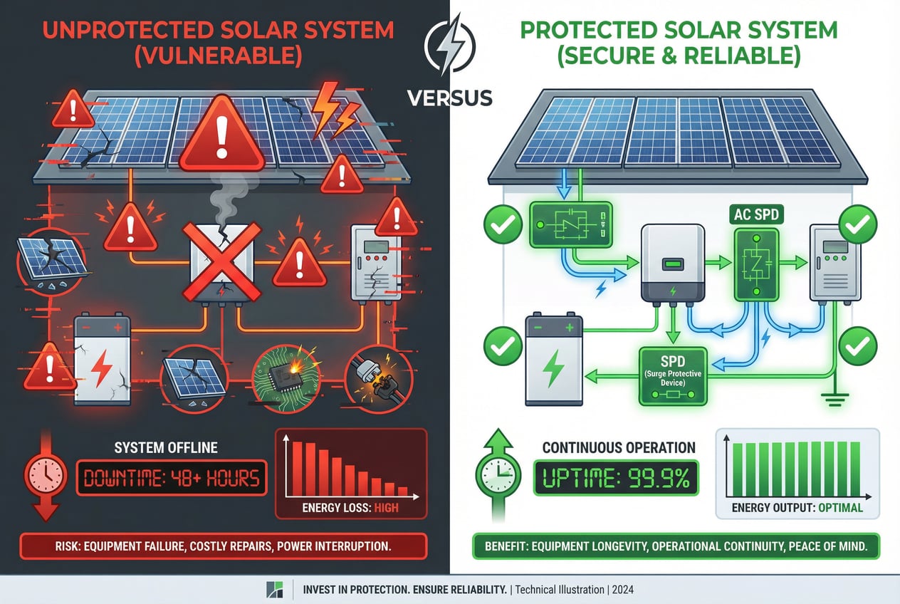
Unprotected System (10-Year Projection):
Protected System (10-Year Projection):
Net Financial Advantage of Protection: $161,000 – $246,000 over 10 years.
This is not speculative. These figures are based on documented industry insurance claim data and field experience from thousands of commercial solar installations. The economics are unambiguous. For every dollar invested in a proper surge protection system, you are protecting eight to ten dollars of potential loss. This is one of the highest-return risk mitigation strategies available to a solar asset owner.
What does unprotected failure actually look like in the field? The images can be stark and sobering.
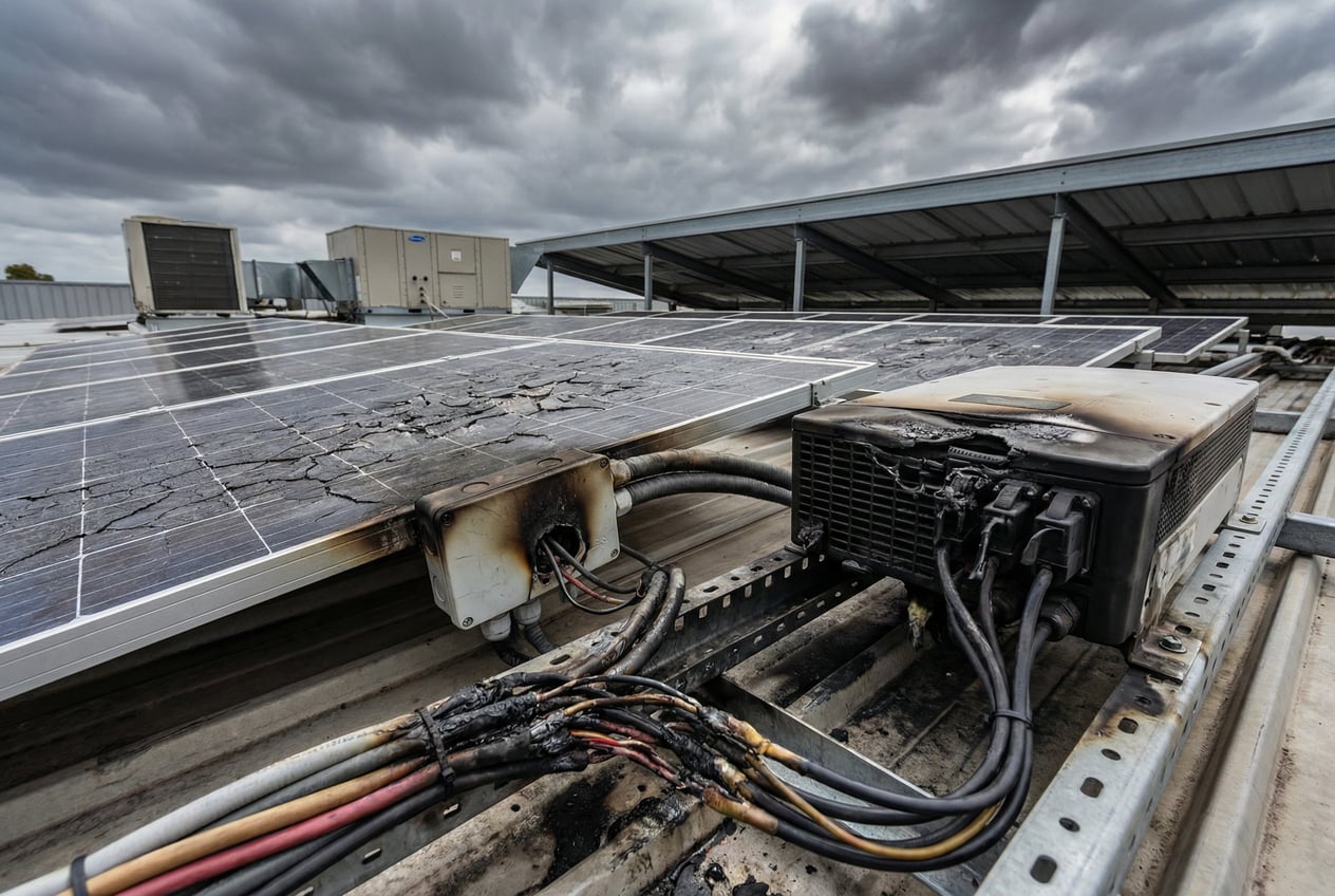
This is not a theoretical risk. These are real installations that experienced real failures. The damaged equipment in this image represents tens of thousands of dollars in direct repair costs. The burn marks on junction boxes, the scorched PCB boards inside inverters, and the melted wiring insulation all tell the same story: an uncontrolled voltage transient found a path through the system and destroyed everything in its path.
Beyond the visible damage, there are hidden costs:
The most tragic aspect of these failures is that they are almost entirely preventable. A properly designed and installed surge protection system would have diverted this energy safely to ground, leaving the equipment unharmed and the system operational. The cost of protection is a fraction of the cost of recovery.
An SPD is only as effective as its installation. Even the highest-quality device will fail to protect if it is incorrectly applied or improperly wired. Here are the critical design and installation considerations that separate a compliant installation from a truly protective one.
1. Grounding is Everything
The foundation of any surge protection strategy is a robust, low-impedance grounding system. An SPD diverts surge current to ground—if the ground connection is poor, the surge has nowhere to go and will find a path through your equipment.
2. Minimize Lead Length
The effectiveness of an SPD is dramatically reduced by long connection leads. The inductance of the wiring creates a voltage drop during fast-rising surge currents, effectively increasing the let-through voltage seen by the protected equipment.
3. Coordination and Cascading
When multiple SPDs are used in a staged approach, they must be properly coordinated to ensure each device operates in its designed surge range without interfering with the others.
4. Location, Location, Location
Strategic placement is as important as device selection.
5. Accessibility and Maintainability
SPDs require periodic inspection and eventual replacement.
6. Code Compliance
Ensure all installations meet the latest NEC and local electrical codes.
A qualified electrical contractor with experience in solar installations should always perform the installation work. This is not a DIY project.
SPDs are sacrificial devices. They absorb surge energy to protect your equipment, and in doing so, they degrade over time. The key to maintaining continuous protection is proactive monitoring and timely replacement.
Inspection Schedule:
Remote Monitoring Integration:
Modern SPDs offer remote monitoring capabilities via dry contact outputs. These can be integrated into your facility’s SCADA or building management system to provide real-time alerts.
Replacement Guidelines:
Documentation:
Maintain a detailed log of all SPD installations, inspections, and replacements. This documentation is valuable for:
If you are a commercial solar system owner, facility manager, or installer reading this article, the question is not whether you need surge protection—the data makes that answer clear. The question is: what are you waiting for?
Every day your solar asset operates without comprehensive surge protection, you are gambling with tens or hundreds of thousands of dollars of equipment and lost production. The average cost of a lightning-related insurance claim is $73,394. The average cost of a comprehensive surge protection system for a commercial installation is $15,000 – $25,000. The return on investment is immediate and profound.
Here’s what you need to do right now:
1. Assess Your Current Protection Status
2. Engage a Qualified Professional
3. Prioritize Quality and Certification
4. Implement a Maintenance Program
5. Document Everything
The cost of doing nothing is simply too high. The technology exists. The best practices are well-established. The financial case is overwhelming. The only variable is your decision to act.
Contact a surge protection specialist today. Request a site assessment. Get a detailed proposal. Implement a protection system that will safeguard your solar investment for decades to come. Your facility, your financial stakeholders, and your peace of mind will all be better for it.
The commercial solar industry has achieved remarkable growth and technological maturity. Systems are more efficient, more reliable, and more economically attractive than ever before. But this success brings with it a heightened exposure to risk. As system sizes grow, as DC voltages increase to 1000V and 1500V, and as facilities become more dependent on their solar assets for both energy and sustainability goals, the consequences of electrical failures become more severe.
Transient overvoltages—from lightning, from grid disturbances, from switching events—are an unavoidable fact of operating a large-scale electrical system. But the damage they cause is not. Surge Protection Devices, properly selected, properly installed, and properly maintained, provide a proven, cost-effective, and essential line of defense.
The case study of Dave’s distribution center is not unique. It is repeated hundreds of times each year across the commercial solar sector. The difference between a $70,000 catastrophic loss and a fully operational, protected system is often a $15,000 investment in comprehensive surge protection. The ROI is not just financial—it is operational, reputational, and strategic.
As solar becomes an increasingly critical component of our energy infrastructure, the imperative to protect these assets will only grow. The tools are available. The knowledge is established. The only question that remains is whether system owners and designers will act proactively, or wait for the next storm—the one they don’t see coming—to force their hand.
The choice is yours. Protect your investment. Protect your business. Protect your future.
This case study is based on aggregated field data, industry research, and engineering best practices. Specific system configurations, protection requirements, and expected outcomes may vary based on location, equipment selection, and installation quality. Always consult with qualified electrical professionals for system-specific recommendations.
