WengYang Industrial Zone Yueqing Wenzhou 325000
Work Hours
Monday to Friday: 7AM - 7PM
Weekend: 10AM - 5PM
WengYang Industrial Zone Yueqing Wenzhou 325000
Work Hours
Monday to Friday: 7AM - 7PM
Weekend: 10AM - 5PM

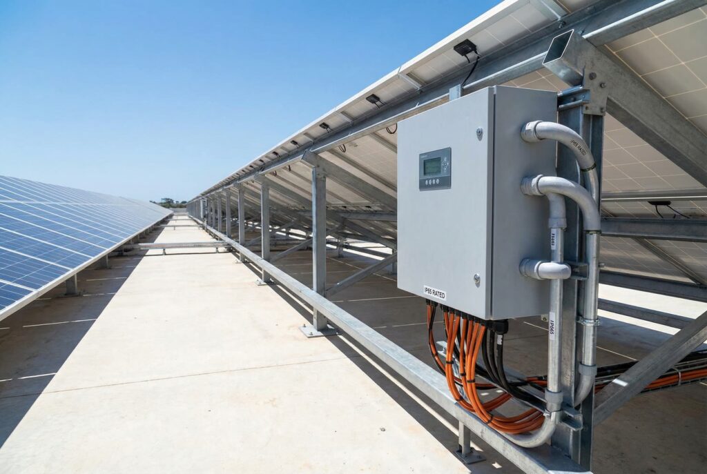
A solar array is a finely tuned system where every component must work in harmony. Yet, one of the most critical components—the PV combiner box—is often misunderstood and incorrectly sized. A mismatched combiner box isn’t just a point of inefficiency; it’s a catastrophic failure waiting to happen. Overloaded circuits, melted components, and even electrical fires can result from improper voltage and current ratings. This isn’t just about code compliance; it’s about the safety, longevity, and performance of your entire solar investment.
This guide provides an exhaustive, engineering-level explanation of how to perfectly match a PV combiner box to your solar array. We’ll walk through the essential NEC-compliant calculations for both voltage and current, explore common mistakes to avoid, and show how choosing a high-quality component like a CNKUANGYA combiner box can ensure your system operates safely and reliably for decades.
Before you can size any component, you must understand the electrical “datasheet” language of the solar modules themselves. These values are the foundation for every calculation you’ll make. Trying to size a combiner box without them is like trying to navigate without a map.
Let’s use a typical high-performance solar panel as an example:
Sample Solar Panel Datasheet
Here’s what these critical parameters mean for system design:
With these foundational parameters defined, we can now move on to the first half of the sizing equation: matching the voltage.
The first and most important step in combiner box selection is ensuring its voltage rating can handle the maximum possible system voltage of your solar array. This is not determined by the panel’s standard Voc, but by its Voc adjusted for the coldest possible temperature at your installation site. Why? Because solar panel voltage increases as temperature decreases. Ignoring this can lead to voltages that exceed component ratings, causing insulation failure and creating a serious safety hazard.
The National Electrical Code (NEC) addresses this in Article 690.7, which mandates that system voltage be calculated for the lowest expected ambient temperature.
Let’s design a string for a location with a record low temperature of -10°C (14°F), using our sample 450W panel (Voc = 49.8V, Temp. Coeff. = -0.25%/°C). Standard Test Conditions (STC) are 25°C.
Step 1: Find the Temperature Difference
Calculate the difference between STC and your record low temperature.
Step 2: Calculate the Voltage Increase Percentage
Multiply the temperature delta by the panel’s temperature coefficient of Voc.
Step 3: Calculate the Temperature-Corrected Voc (Voc_corrected)
Increase the standard Voc by the calculated percentage. This is the true maximum voltage a single panel can produce on the coldest day.
Step 4: Determine Maximum String Size
Divide the target system voltage (e.g., 1000V for many commercial systems) by the corrected Voc per panel. Always round down to the nearest whole number.
Step 5: Calculate the Final Maximum System Voltage
Multiply the number of panels in your string by the corrected Voc to find your worst-case string voltage.
Step 6: Select the Combiner Box
Choose a combiner box with a DC voltage rating higher than your calculated maximum system voltage.
Once the voltage is handled, you must size the overcurrent protection devices (OCPDs) and conductors. This involves two levels: protecting each individual string and protecting the main output that combines all strings. This is governed by NEC 690.8 (Circuit Sizing) and 690.9 (Overcurrent Protection).
The core principle is to account for the fact that solar circuits are considered “continuous duty” and can experience elevated current due to sun irradiance levels exceeding the 1000 W/m² STC standard. This is why we use a “double 125%” or 1.56 multiplier.
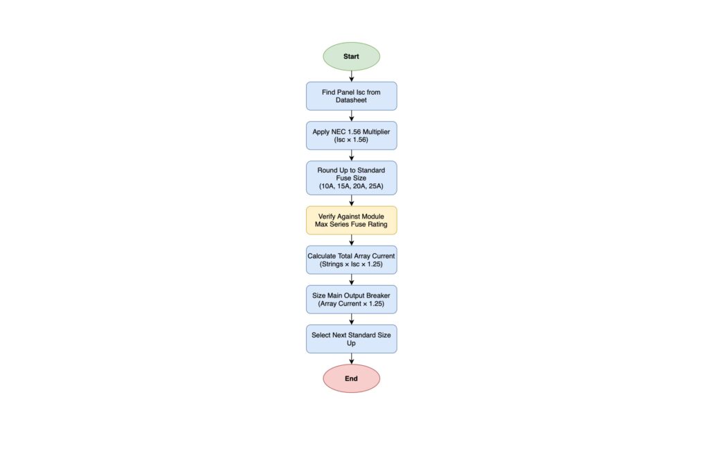
Each string entering the combiner box must be protected. The formula is:
Minimum Fuse Rating = Isc × 1.56
Step-by-Step String Fuse Calculation
Using our sample panel with Isc = 11.4A:
Step 1: Calculate the Minimum Fuse Rating
Step 2: Select the Next Standard Fuse Size
You cannot buy a 17.78A fuse. You must round up to the next standard DC fuse size available. Common DC fuse sizes are 15A, 20A, 25A, and 30A.
This calculation is repeated for every string connected to the combiner box. If your combiner has 12 inputs, you will need 12 of these 20A fuses.
The main output conductor and its associated disconnect or breaker must be sized to handle the combined current of all strings.
Step-by-Step Main Output Calculation
Let’s assume we are designing a system with 8 strings.
Step 1: Calculate Total Maximum Array Current
This calculation requires a 1.25 safety factor on the sum of all string currents.
Step 2: Select the Main Breaker/Disconnect Rating
The output breaker or fused disconnect must have a rating of at least this value. You’ll choose the next standard size up.
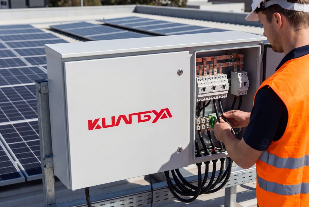
A quality combiner box from CNKUANGYA is pre-engineered with appropriately sized busbars to handle these combined currents without overheating, ensuring a safe and efficient transition of power.
To streamline your design process, here are some quick-reference tables based on the principles discussed.
Table 1: Voltage Sizing Examples (1000V Target System)
| Panel Voc (STC) | Panels per String | Record Low Temp. | Temp Corrected Voc (Panel) | Max System Voltage | Required Combiner Rating |
|---|---|---|---|---|---|
| 49.8V | 18 | -10°C | 54.2V | 975.1V | 1000V DC |
| 48.5V | 19 | -5°C | 51.5V | 978.5V | 1000V DC |
| 41.2V | 22 | 0°C | 43.8V | 963.6V | 1000V DC |
Table 2: String Fuse Sizing Examples
| Panel Isc | Min. Fuse Rating (Isc x 1.56) | Selected Standard DC Fuse |
|---|---|---|
| 9.5A | 14.82A | 15A |
| 11.4A | 17.78A | 20A |
| 13.2A | 20.59A | 25A |
Table 3: Combiner Main Lug/Breaker Sizing Examples
| Number of Strings | Panel Isc | Total Max Current ((Strings x Isc) x 1.25) | Selected Main Breaker |
|---|---|---|---|
| 4 | 11.4A | 57A | 60A or 70A |
| 8 | 11.4A | 114A | 125A |
| 12 | 11.4A | 171A | 175A or 200A |
Even seasoned professionals can make mistakes. Here are five common errors we see in the field and why they are so dangerous:
Isc x 1.56 factor for continuous duty. Undersized wires will overheat, posing a significant fire risk.Case Study 1: Residential Rooftop in a Harsh Climate
Case Study 2: Commercial Ground-Mount Efficiency
“As an installer, time is money. CNKUANGYA’s combiners are a dream to work with. The knockouts are clean, there’s plenty of room for bending radius, and the terminals are robust. I can trust the quality, and my installations go faster. It’s a no-brainer.”
— John P., Lead Installer, Apex Solar Solutions
“From an engineering perspective, CNKUANGYA’s spec sheets are clear and their components are top-notch. I specified their 1500V combiners with integrated disconnects for a large-scale project, and the reduction in balance-of-system costs was significant. Their products are robust, compliant, and reliable.”
— Maria E., P.E., Senior Electrical Engineer, Sunstone Engineering Group
“We had a CNKUANGYA combiner box installed with our ground-mount system five years ago. It has operated flawlessly through freezing winters and scorching summers. Knowing that the heart of our solar array is protected by such a durable component gives us incredible peace of mind.”
— David L., Farm Owner
Use this checklist on every job to ensure a safe, reliable, and code-compliant installation.
In a solar PV system, there is no room for “close enough.” Correctly sizing your PV combiner box is not an optional detail—it is fundamental to the safety, performance, and bankability of your project. By diligently applying the NEC-compliant formulas for voltage and current, you protect your investment from catastrophic failure and ensure it operates at peak efficiency.
Don’t let a simple component compromise a complex system. Choosing a robust, pre-engineered, and certified combiner box from a trusted manufacturer like CNKUANGYA simplifies this critical step. With high-quality materials, thoughtful design, and a range of solutions for any system size, you can build with confidence, knowing that your array is both powerful and protected.
Ready to build a safer, more reliable solar array? Browse our full range of 600V, 1000V, and 1500V PV Combiner Boxes or contact our technical support team for help with your next system design.
