WengYang Industrial Zone Yueqing Wenzhou 325000
Work Hours
Monday to Friday: 7AM - 7PM
Weekend: 10AM - 5PM
WengYang Industrial Zone Yueqing Wenzhou 325000
Work Hours
Monday to Friday: 7AM - 7PM
Weekend: 10AM - 5PM
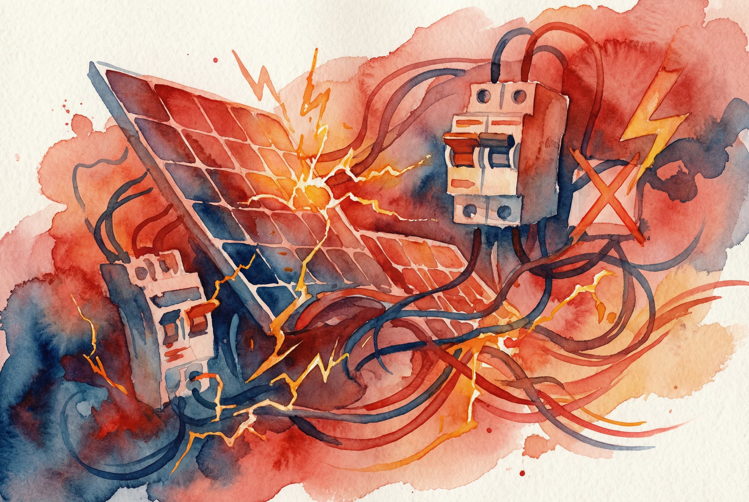
Through the lens of a thermal camera, the box was a disaster zone. While the ambient rooftop temperature was a blistering 104°F (40°C), the terminals inside the combiner were glowing at a terrifying 350°F (180°C). A post-mortem analysis showed the root cause: improperly torqued terminal lugs. Two years of daily thermal cycling—the expansion and contraction from solar heating—had progressively loosened the connections. This created high-resistance points that acted like miniature heating elements, slowly cooking the components until the entire assembly was on the verge of a catastrophic fire.
This scenario is my world. As a senior application engineer, I’ve been called to investigate dozens of failures just like this one. The hard truth is that while solar technology is more reliable than ever, the unique physics of Direct Current (DC) are unforgiving. Unlike the alternating current (AC) that powers our buildings, DC doesn’t naturally extinguish its own arc, making it far more dangerous when mishandled.
The good news is that these failures are almost entirely preventable. They don’t stem from exotic phenomena, but from a handful of common, fundamental mistakes made during the design and installation phase. This guide is a collection of the top 10 mistakes I see in the field every year. Master these concepts, and you’ll not only ensure the safety and longevity of your systems but also elevate yourself as a true professional in this industry.
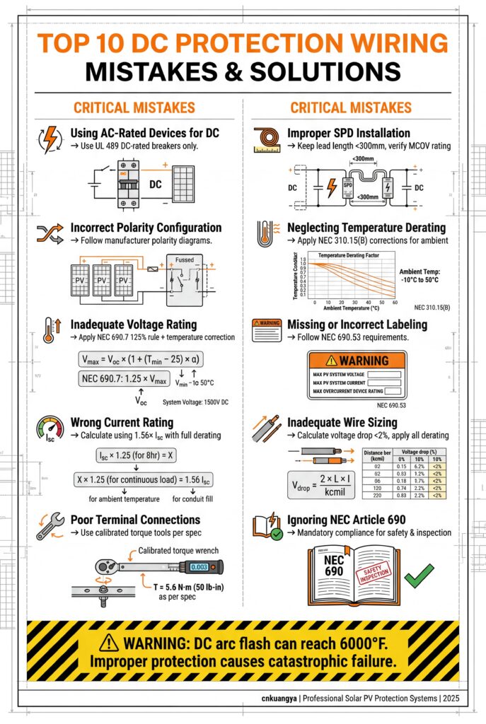
This is arguably the most common and dangerous mistake a new installer can make. Grabbing a standard AC-rated circuit breaker from the truck and installing it in a DC combiner box is a recipe for disaster.
The Mistake: Assuming that a breaker is a breaker. Installers use AC-rated fuses, breakers, or switches in DC circuits, often because they are cheaper or more readily available.
Why It’s Dangerous: AC and DC are fundamentally different. AC current passes through zero 120 times per second (in a 60Hz system). This “zero-crossing” moment provides an opportunity for an overcurrent protection device to extinguish the electrical arc that forms when its contacts open. A DC current, by contrast, is a continuous, relentless flow. When a DC device opens under load, it must stretch and cool the arc entirely on its own, without a zero-crossing to help. An AC breaker used in a DC circuit will likely fail to clear a fault, allowing a sustained arc to form. This arc is essentially plasma, reaching thousands of degrees, which will melt the device, burn through the enclosure, and ignite a fire.

The Solution:
| Feature | AC Circuit Breaker | DC Circuit Breaker |
|---|---|---|
| Arc Quenching | Relies on AC zero-crossing | Uses magnets, larger arc chutes |
| Polarity | Not polarized | Often polarized (must be wired correctly) |
| Listing | UL 489, IEC 60947-2 | UL 489B, IEC 60947-2 (with DC rating) |
| Typical Use | Building distribution panels | Solar PV combiners, battery banks |
Key Takeaway: If it doesn’t say DC, don’t use it. Period.
Voltage is electrical pressure. If the pressure is higher than what your container is rated for, it will fail. In a PV system, this failure can be explosive.
The Mistake: Selecting protection devices with a voltage rating lower than the maximum possible system voltage.
Why It’s Dangerous: The voltage of a solar panel string is not constant. It is highest at open-circuit (Voc) and increases in cold weather. NEC Article 690.7 requires installers to calculate the maximum system voltage based on the lowest expected ambient temperature for the site. A 600VDC-rated breaker installed in a system that can reach 650VDC on a cold winter morning is a critical failure waiting to happen. An overvoltage condition can cause the device to fail to interrupt a fault, leading to an arc flash, or can cause a dielectric breakdown, where the insulation inside the device fails catastrophically.
The Solution:
Pro-Tip: Always add a safety margin. If your calculated max voltage is 590V, don’t use a 600V device. Step up to the next standard rating (e.g., 800V or 1000V) for enhanced safety and reliability.
In the world of DC, direction matters. Many DC circuit breakers are “polarized,” meaning they are designed to have current flow through them in only one direction.
The Mistake: Wiring a polarized DC breaker backward, connecting the source to the load terminal and vice versa.
Why It’s Dangerous: Polarized breakers contain small permanent magnets. These magnets are strategically placed to help push the electrical arc into the “arc chute” when the contacts open. The arc chute is a chamber of metal fins designed to stretch, cool, and extinguish the arc. If you wire the breaker backward, the magnets will push the arc in the opposite direction—away from the arc chute and directly into the flammable plastic body of the breaker itself. This will instantly destroy the breaker and almost certainly cause a fire inside the enclosure.
The Solution:
Key Takeaway: On a polarized DC breaker, LINE and LOAD are not suggestions—they are a critical safety requirement.
Sizing overcurrent protection devices (OCPDs) for solar circuits is not the same as sizing for standard AC loads. Using the wrong math can lead to either nuisance tripping or, worse, a complete failure to protect the circuit.
The Mistake: Sizing a fuse or breaker based only on the panel’s nameplate current (Isc) or using standard AC sizing rules.
Why It’s Dangerous: Solar circuits are considered a continuous load and are subject to “edge of cloud” effects, where passing clouds can cause a temporary increase in irradiance, boosting current output. NEC Article 690.9(A) mandates a specific sizing formula to account for both factors. Sizing a fuse too small will cause it to blow under normal peak conditions (nuisance trip). Sizing it too large will fail to protect the conductors from overheating during a fault, creating a fire hazard.
The Solution: The NEC dictates a two-part calculation, which combines to a single multiplier: 1.56.
Required Rating = Isc × 1.25 (for continuous load) × 1.25 (for over-irradiance) = Isc × 1.56Required Rating = 9.8A × 1.56 = 15.29A| Sizing Example | Improper Sizing (Isc only) | Proper Sizing (NEC 1.56x Rule) |
|---|---|---|
| String Isc | 9.8A | 9.8A |
| Calculation | Select nearest size to 9.8A -> 10A fuse | 9.8A * 1.56 = 15.29A |
| Selected OCPD | 10A Fuse | 20A Fuse (next standard size up) |
| Result | Nuisance tripping on sunny days | Safe, reliable operation |
Pro-Tip: Always check the module’s datasheet for the “Maximum Series Fuse Rating.” Your calculated OCPD size must not exceed this value. If it does, your string design is flawed.
The current rating stamped on a breaker or fuse is only valid at a specific, controlled ambient temperature (typically 40°C for breakers, 25°C for fuses). A combiner box on a black commercial roof in Texas is not a controlled environment.
The Mistake: Failing to adjust the current-carrying capacity of a protection device for the actual ambient temperature inside the enclosure.
Why It’s Dangerous: Heat is the enemy of electrical components. A circuit breaker that is rated for 100A at 40°C might only be able to handle 85A continuously when the temperature inside the combiner box reaches 60°C (140°F). If you’re pushing 90A through it, the breaker’s internal thermal trip mechanism will activate, causing a nuisance trip. This leads to system downtime and expensive troubleshooting calls. For fuses, high ambient temperatures can degrade the fuse element over time, causing it to fail prematurely.
The Solution:
Effective Rating = Nominal Rating × Correction Factor. To size correctly, you must work backward: Required Nominal Rating = Circuit Amps / Correction Factor.Required Nominal Rating = 40A / 0.85 = 47A. You would need to select a 50A breaker to safely handle 40A in that hot environment.| Ambient Temp | Correction Factor | 100A Breaker’s True Capacity |
|---|---|---|
| 40°C (104°F) | 1.0 | 100A |
| 50°C (122°F) | 0.92 | 92A |
| 60°C (140°F) | 0.85 | 85A |
| 70°C (158°F) | 0.77 | 77A |
Key Takeaway: Assume your combiner will be hot and size your protection devices accordingly. The nameplate rating is a starting point, not the final answer.