Introduction: The Critical Role of Proper PV Combiner Box Layout
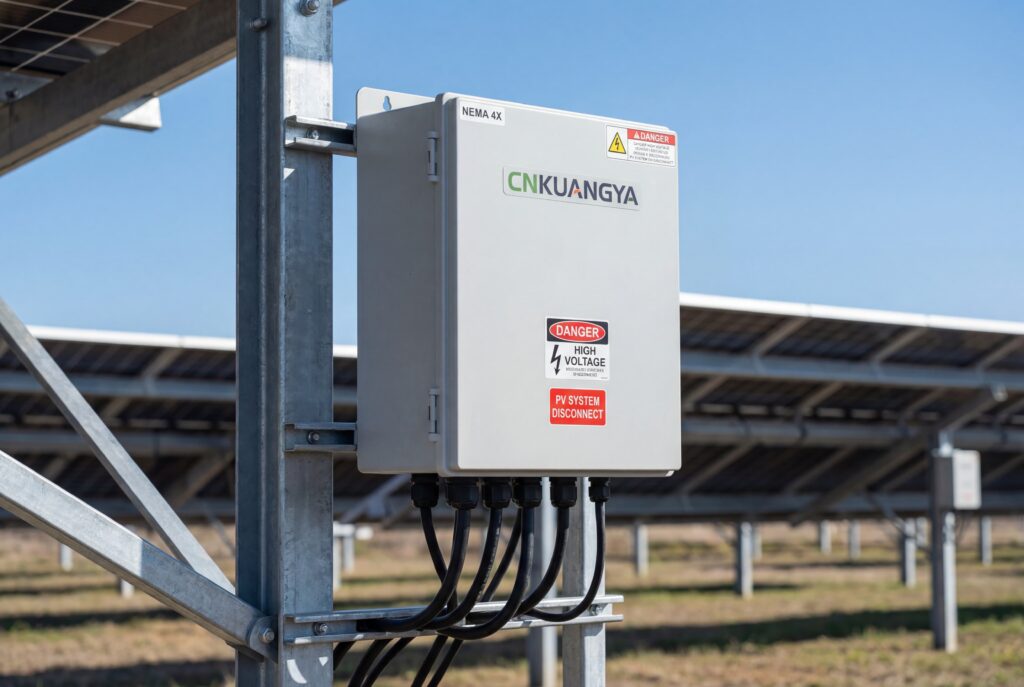
In photovoltaic installations, the combiner box serves as a critical junction point where multiple solar panel strings converge before connecting to the inverter. A poorly designed or improperly wired combiner box can lead to power losses, safety hazards, code violations, and system failures. Whether you’re installing a residential rooftop array or a commercial solar farm, understanding the proper layout and wiring of a PV combiner box is essential for optimal system performance and long-term reliability.
This comprehensive guide will walk you through every aspect of PV combiner box design, from component selection to NEC compliance, complete with detailed wiring diagrams and professional installation practices used by industry experts.
A PV combiner box (also called a solar combiner box or DC combiner box) is an electrical enclosure that consolidates the output from multiple photovoltaic strings into a single DC circuit. This consolidated output then feeds into the inverter or charge controller.
Primary Functions
The combiner box serves several critical functions in a solar array:
String Consolidation: Combines multiple DC strings into fewer conductors, reducing wire runs to the inverter
Overcurrent Protection: Houses fuses or circuit breakers for each string to prevent reverse current and overcurrent conditions
Isolation and Safety: Provides a central disconnect point for maintenance and emergency shutdown
Surge Protection: Accommodates SPD (Surge Protective Devices) to protect against lightning and voltage spikes
Monitoring Integration: Enables string-level monitoring for performance optimization
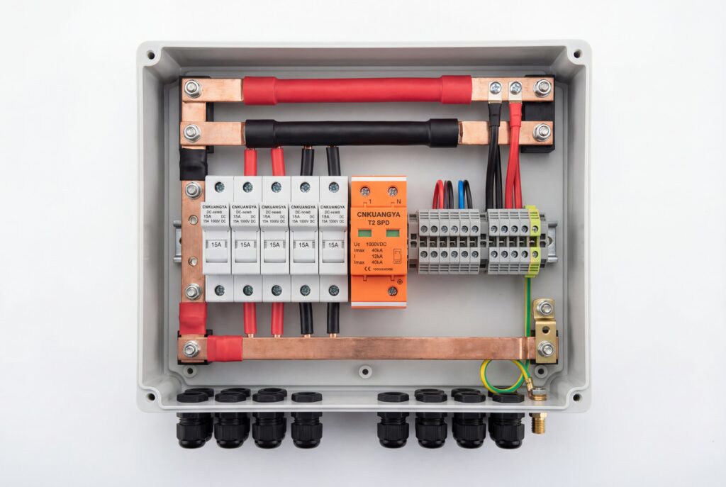
Key Components and Materials
Understanding the components that make up a proper combiner box is fundamental to correct installation and layout.
Essential Components
Component
Function
Typical Rating
NEC Reference
Enclosure
Weather-resistant housing
NEMA 3R/4/4X
690.14
String Fuses
Overcurrent protection per string
10-20A, 600-1000VDC
690.9
Busbar
Common negative and positive connection points
Rated for total system current
690.47
Disconnect Switch
Manual isolation capability
Load-break rated
690.13
SPD Module
Transient voltage surge suppression
Type 1 or 2, appropriate Vdc
690.35
Terminal Blocks
Wire connection points
Current and voltage rated
110.14
Grounding Lug
Equipment grounding connection
Suitable for conductor size
690.43
Cable Glands
Weatherproof cable entry
IP67/IP68 rated
690.31
Material Specifications
Enclosure Materials:
Fiberglass (FRP): UV-resistant, non-conductive, excellent for coastal environments
Aluminum: Lightweight, corrosion-resistant with powder coating
Stainless Steel: Superior durability for harsh industrial environments
Polycarbonate: Cost-effective, good UV resistance for residential applications
Conductor Materials:
USE-2 or PV wire rated for 90°C, 600V minimum (1000V for systems >600V)
Copper conductors preferred for lower resistance
UV-resistant jacket for exposed runs
Enclosure Selection Guide
Selecting the appropriate enclosure is critical for system longevity and code compliance.
Enclosure Rating Comparison
NEMA Rating
Protection Level
Best Applications
Cost Factor
NEMA 3R
Rain, sleet, ice, dust
Outdoor residential, protected locations
$
NEMA 4
Wind-driven rain, hose-directed water, dust
General commercial outdoor
$$
NEMA 4X
NEMA 4 + corrosion resistance
Coastal, industrial, high-humidity
$$$
NEMA 6P
Submersion, dust-tight
Flood-prone areas, extreme weather
$$$$
Sizing Considerations
Minimum Internal Dimensions Formula:
Required Volume = (Number of Components × Component Volume) × 1.5 (working space factor)
Typical Sizing:
6-string combiner: 16″ × 12″ × 8″ minimum
12-string combiner: 20″ × 16″ × 10″ minimum
24-string combiner: 24″ × 20″ × 12″ minimum
Wire Sizing and Specifications
Proper wire sizing is crucial for safety, efficiency, and code compliance.
Wire Sizing Table (Based on NEC Article 690)
String Current (Isc)
Min. Wire Size (Copper, 90°C)
Fuse Rating
Max Voltage Drop
8-10A
10 AWG
15A
2%
11-13A
8 AWG
20A
2%
14-17A
6 AWG
25A
2%
18-22A
4 AWG
30A
2%
23-30A
2 AWG
40A
2%
Important Calculation:
Minimum Wire Ampacity = Isc × 1.56 (125% × 125% per NEC 690.8)
Temperature Derating
Combiner boxes in direct sunlight may experience ambient temperatures of 60-70°C. Apply NEC Table 310.15(B)(2)(a) correction factors:
40°C ambient: 0.91 correction factor
50°C ambient: 0.82 correction factor
60°C ambient: 0.71 correction factor
PV System Architecture with Combiner Box Placement
Verify Shutdown: Confirm PV disconnect is open and locked out
Test for Voltage: Use properly rated voltmeter to verify no voltage present
Wait for Dissipation: Allow capacitance to discharge (wait 5 minutes minimum)
Use PPE: Wear arc-rated clothing, insulated gloves rated for voltage
Have Tools Ready: Insulated tools, voltage tester, flashlight
During Maintenance:
Never work alone on live DC circuits
Always assume circuits are live until proven otherwise
Use one-hand rule when possible to reduce shock path
Keep combustible materials away from DC terminations
Never bypass or remove safety devices
DC-Specific Hazards:
DC arc-flash can be more persistent than AC
No zero-crossing means arc interruption is more difficult
Higher voltages (600-1000VDC) increase shock and arc-flash risk
Capacitive storage can maintain voltage after disconnect
Advanced Considerations
Monitoring Integration
Modern combiner boxes can integrate string-level monitoring:
Current sensors: Hall effect or shunt-based per string
Voltage monitoring: Individual string voltage measurement
Communication protocols: RS485, Modbus, or proprietary systems
Alarm outputs: Fault indication to central monitoring
Future-Proofing Design
Consider these factors for long-term flexibility:
Oversized enclosure: 20-30% extra space for future expansion
Rated for higher voltage: Use 1500VDC components for 1000VDC systems
Modular busbar design: Easier to add strings later
Standardized components: Easier parts sourcing and replacement
Environmental Optimization
Coastal Installations:
Use NEMA 4X stainless steel enclosures
Apply corrosion-resistant coatings to busbars
Use marine-grade cable glands
Increase inspection frequency
Desert/High-UV Locations:
Select UV-stabilized enclosures
Use high-temperature rated components (105°C)
Provide shade structure if possible
Increase temperature derating factors
Cold Climate Considerations:
Verify components operate at minimum temperatures
Consider heated enclosures for extreme cold
Ensure cable remains flexible at low temperatures
Account for thermal expansion/contraction
Frequently Asked Questions (FAQ)
Q1: What’s the difference between a combiner box and a recombiner box?
A: A combiner box consolidates multiple PV strings into a single output for connection to one inverter. A recombiner box combines the outputs from multiple inverters or combiners into a single main feeder, typically used in large commercial or utility-scale installations. Combiners operate at DC voltage (pre-inverter), while recombiners typically operate at AC voltage (post-inverter).
Q2: Do I need a combiner box for a residential solar installation?
A: Not always. Residential systems with 2-3 strings can often connect directly to string inverter inputs. However, you should use a combiner box when:
You have 4+ strings
String home runs exceed 50 feet
You need centralized disconnect/monitoring
Local code requires accessible string-level isolation
Using a central inverter instead of microinverters
Q3: Can I use AC-rated fuses in a DC combiner box?
A: No. AC fuses are designed to interrupt current at zero-crossing (60Hz), which doesn’t occur in DC circuits. DC fuses must have adequate voltage rating (minimum 1.25 × Voc) and must be listed for DC operation. Using AC fuses in DC applications creates serious safety hazards and violates NEC 690.9.
Q4: How do I size the main output conductors from the combiner box?
A: Follow this calculation per NEC 690.8:
Main Conductor Ampacity = (Sum of all string Isc) × 1.25 × 1.25 = Total Isc × 1.56
Then select conductor size from NEC Table 310.16 (or 310.15 for other conditions) that meets or exceeds this ampacity, applying any applicable temperature correction factors.
Q5: What’s the difference between Type 1 and Type 2 SPDs for PV applications?
A:
Type 1 SPD: Tested to withstand direct lightning strikes (higher energy), typically installed at service entrance or main distribution. More expensive, larger form factor.
Type 2 SPD: Designed for indirect surges and switching transients. Most common in PV combiner boxes. More economical, compact design.
For typical rooftop PV systems with proper lightning protection grounding, Type 2 SPDs in the combiner box are usually sufficient.
Q6: Should the combiner box be grounded or ungrounded system?
A: This depends on your system design:
Grounded systems (one conductor bonded to ground): More traditional, required for some older inverter types, provides more straightforward fault protection
Ungrounded systems (no conductor grounded): Increasingly common with modern transformerless inverters, requires ground-fault protection per NEC 690.35, allows continued operation during single ground fault
Follow your inverter manufacturer specifications. Most modern string inverters use ungrounded PV arrays.
Q7: How often should I replace fuses in a combiner box?
A: Fuses should only be replaced:
After they’ve blown (indicating fault or overcurrent condition)
During troubleshooting if fuse integrity is questionable
If visual inspection shows damage or corrosion
Do NOT replace fuses on a regular schedule – they’re designed to last the system lifetime under normal operation. However, inspect fuse holder contacts annually and clean if oxidation is present.
Q8: Can I install the combiner box in direct sunlight?
A: Yes, but with considerations:
Use properly rated enclosure (NEMA 3R minimum, 4 or 4X preferred)
Apply temperature derating to conductor sizing (may reach 70°C+ ambient)
Select components rated for high operating temperatures
Consider mounting on north-facing wall or providing shade
Use light-colored enclosures to reflect heat
Ensure adequate ventilation (don’t seal vents)
The enclosure WILL get hot – this affects wire ampacity and component lifespan.
Q9: What are the most common code violations found during inspection?
A: Based on field experience, common violations include:
Undersized conductors (failing to apply 1.56 factor)
Missing or inadequate labeling (NEC 690.53)
AC-rated components in DC application
Insufficient working clearance (NEC 110.26)
Missing or improperly sized equipment grounding conductor
Inadequate wire identification/marking
Mixed wire sizes under single terminal
Missing or damaged enclosure seals/gaskets
Q10: How do I troubleshoot low output from one string?
A: Follow this systematic approach:
Check the combiner box:
Verify fuse continuity for that string
Check for loose connections at terminals
Measure string voltage (should be near Voc with no load)
Measure string current (should be near Isc when shorted)
Inspect the array:
Look for shading issues
Check for soiling/debris on panels
Inspect for physical damage
Verify panel connections are tight
Isolate the problem:
Compare to adjacent strings (similar production expected)
Use thermal imaging to identify hot spots
Check individual panel voltages to find weak/failed panels
Common causes:
Blown fuse (most common, easiest fix)
Loose connection causing high resistance
Failed panel in string
Damaged cable between array and combiner
Corroded terminals
Conclusion
Proper layout and wiring of a PV combiner box is fundamental to safe, efficient, and code-compliant solar installations. By following the principles outlined in this guide—from component selection and wire sizing to NEC compliance and professional installation practices—you can ensure optimal system performance and long-term reliability.
Remember these key takeaways:
Size all conductors at 156% of short-circuit current (Isc × 1.56)
Use only DC-rated components listed for PV applications
Maintain proper spacing and clearances per NEC requirements
Label everything clearly and completely
Consider environmental factors in component selection
Follow manufacturer torque specifications for all connections
Perform regular maintenance and inspections
Whether you’re a solar installer, electrical contractor, or system designer, mastering combiner box layout is an essential skill that directly impacts system safety, performance, and compliance. Use the diagrams and specifications in this guide as a reference for your next installation.
For more technical resources and product specifications for solar installations, visit cnkuangya.COM for industry-leading electrical components and expert guidance.
elaine
Head of Marketing at Kuangya, focused on the global promotion of electrical protection and power distribution solutions.● Core Areas: Brand building in the PV, energy storage, and industrial power markets. ● Professional Products: Fuses, Surge Protective Devices (SPD), Miniature Circuit Breakers (MCB), and transfer switches. ● Value Proposition: Serving the global renewable energy market with "Safety, Reliability, and Innovation" as our cornerstones.Welcome to connect and collaborate to jointly advance the progress of intelligent power distribution technology.